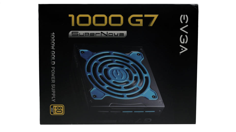
EVGA SuperNOVA 1000 G7 Power Supply Review
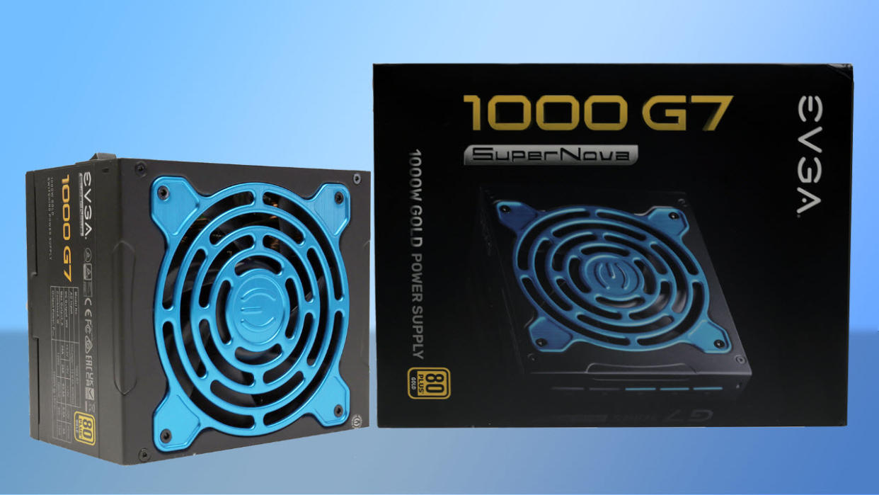
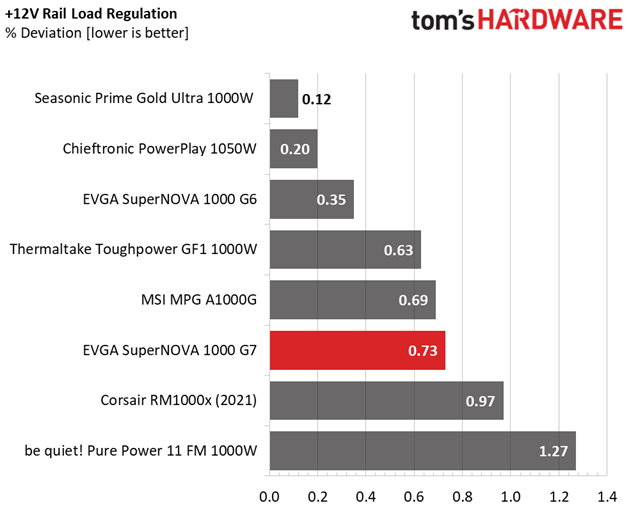
The EVGA SuperNOVA 1000 G7 is a high-performance power supply, challenging some of the highest capacity models on our best PSUs,list. FSP delivered an excellent platform to EVGA with tiny dimensions and high build quality. The strongest competitor is the Corsair RM1000x (2021), which delivers the same performance levels with notably lower noise output.
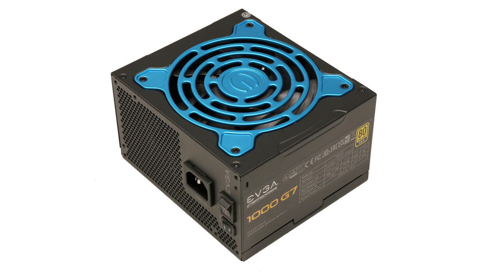
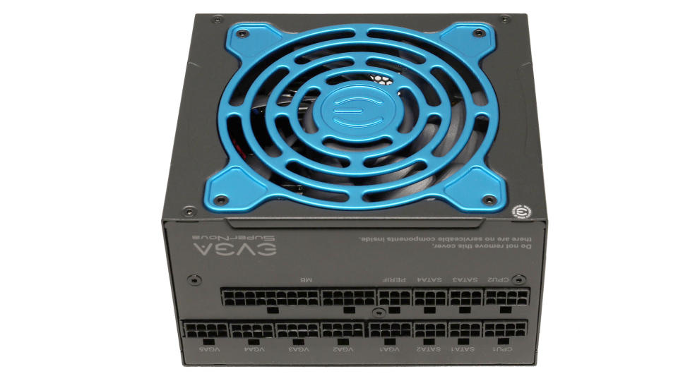
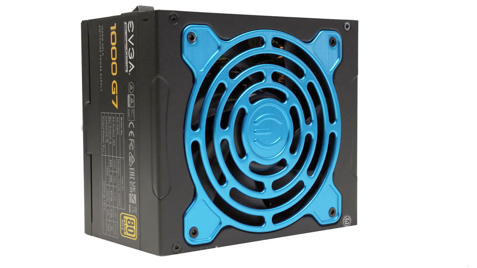
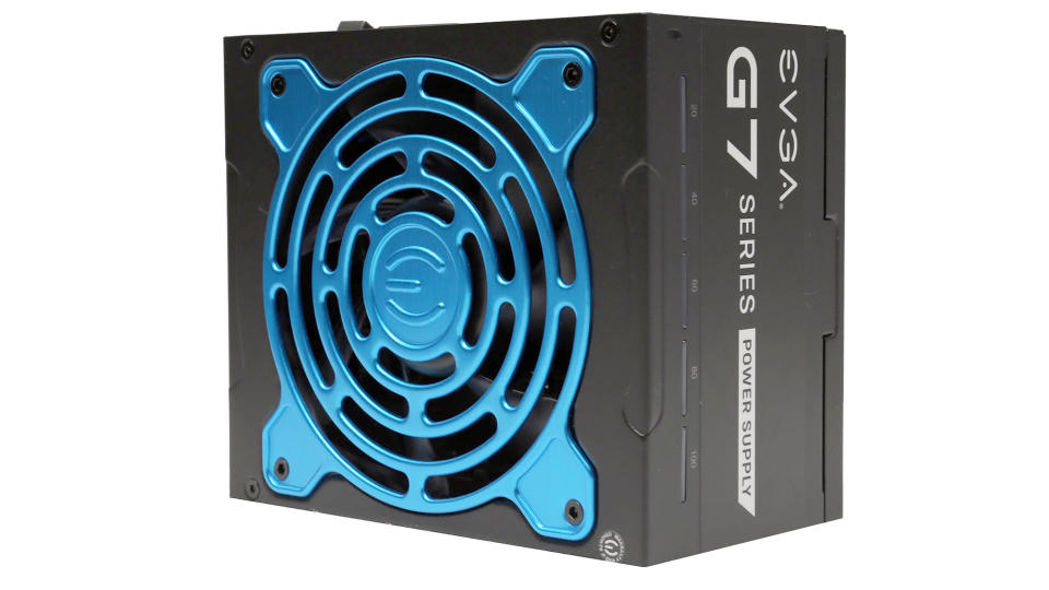
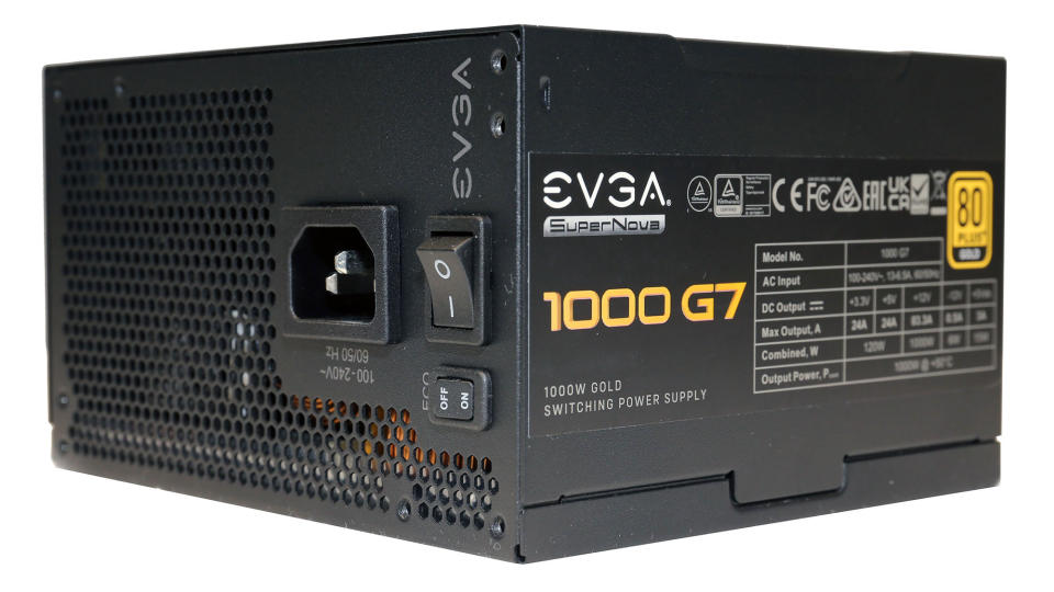
After numerous EVGA G series revisions, we have reached G7, with FSP providing the platforms. The G7 units come in four flavors, ranging from 650 W to 1,000 W. All have super compact dimensions, with only 130mm depth, the same as the SFX-L form factor. The dimensions of the 1000 G7 unit, which I will evaluate in this review, are 150 (W) x 85 (H) x 130 mm (L). In comparison the SilverStone SX1000 SFX-L measures 125 x 65 x 130 mm. This makes the 1000 G7 the smallest 1,000 W ATX PSU available on the market. One might wonder why vendors keep making smaller power supplies when very specific standards define the dimensions, but as long as it doesn't affect noise output and performance, I don't mind.
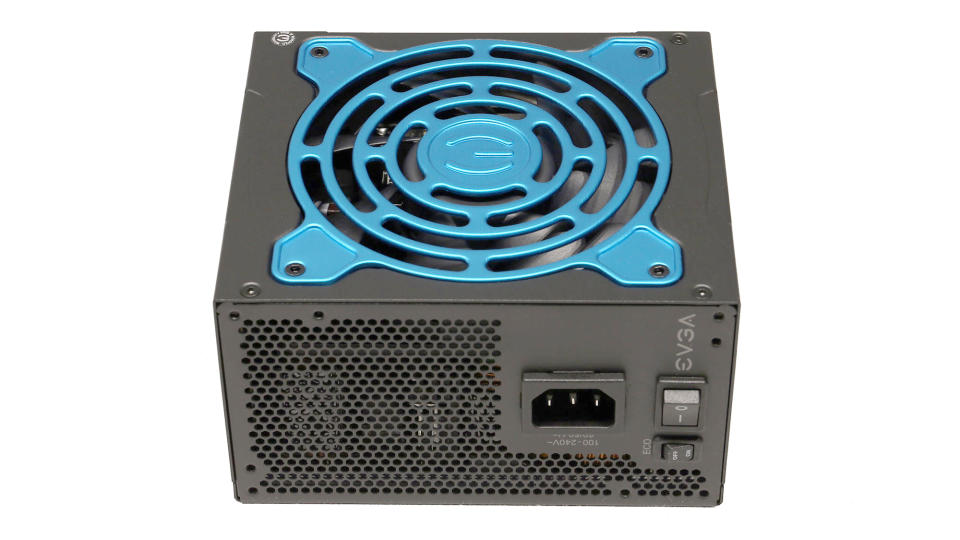
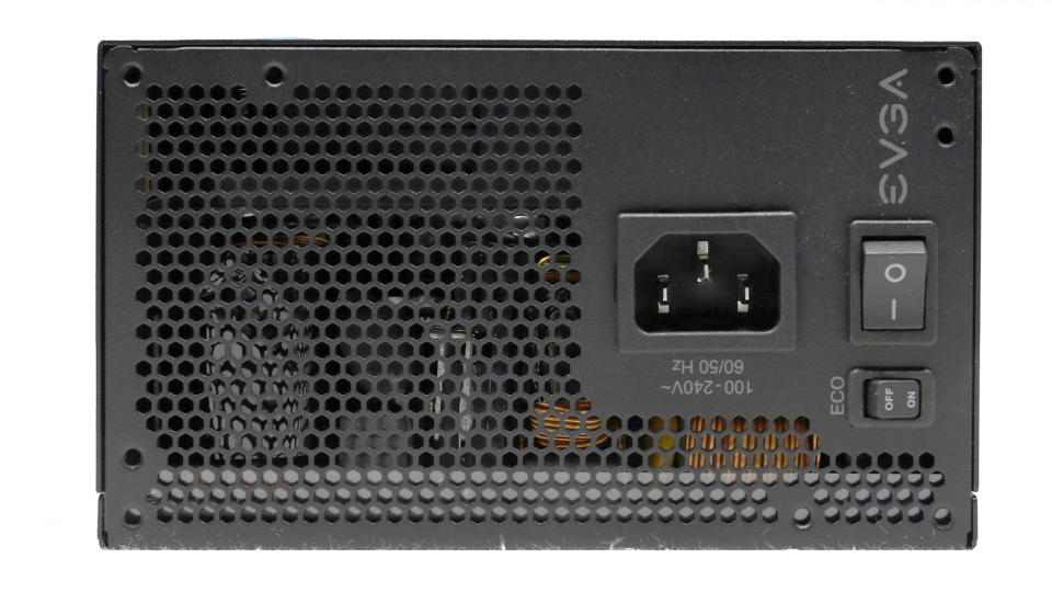
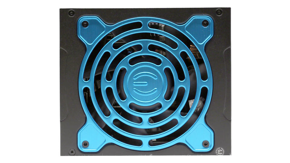
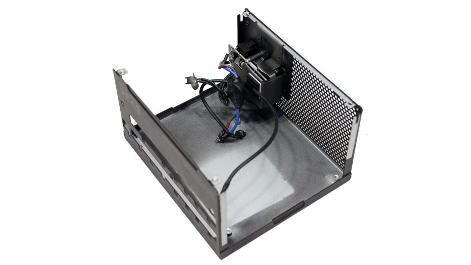
There was no room for a larger fan, so FSP had to install 120 mm fans. Thanks to their fluid dynamic bearings, they shouldn't have a problem with the prolonged, 10-year warranty. EVGA was among the first to offer such long warranty periods, along with Corsair and Seasonic.

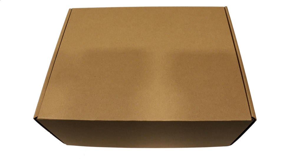
The product's box is small, although it contains a powerful 1,000 W PSU. The protection inside is good, with foam spacers covering the PSU's edges.

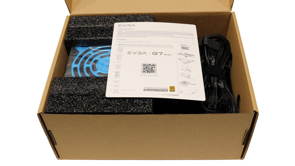
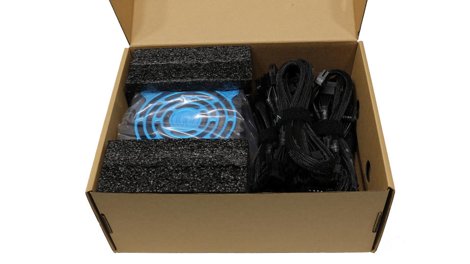
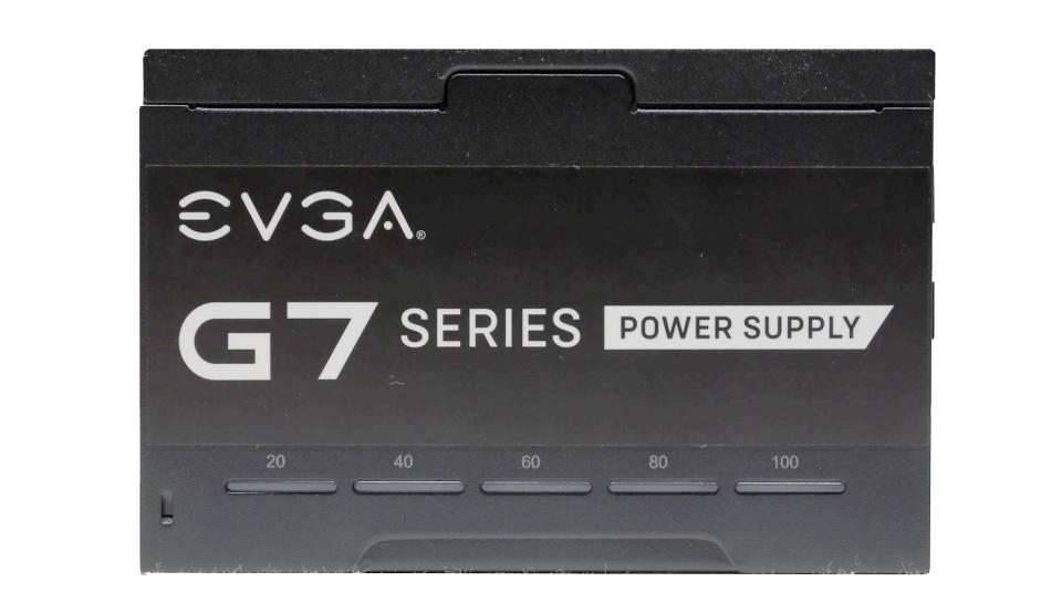
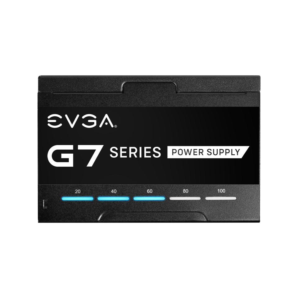
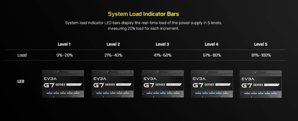
Once you take the PSU out of the box, you will also notice some LED indicators, which depict the load level of the PSU.
Specifications
Manufacturer (OEM) | FSP |
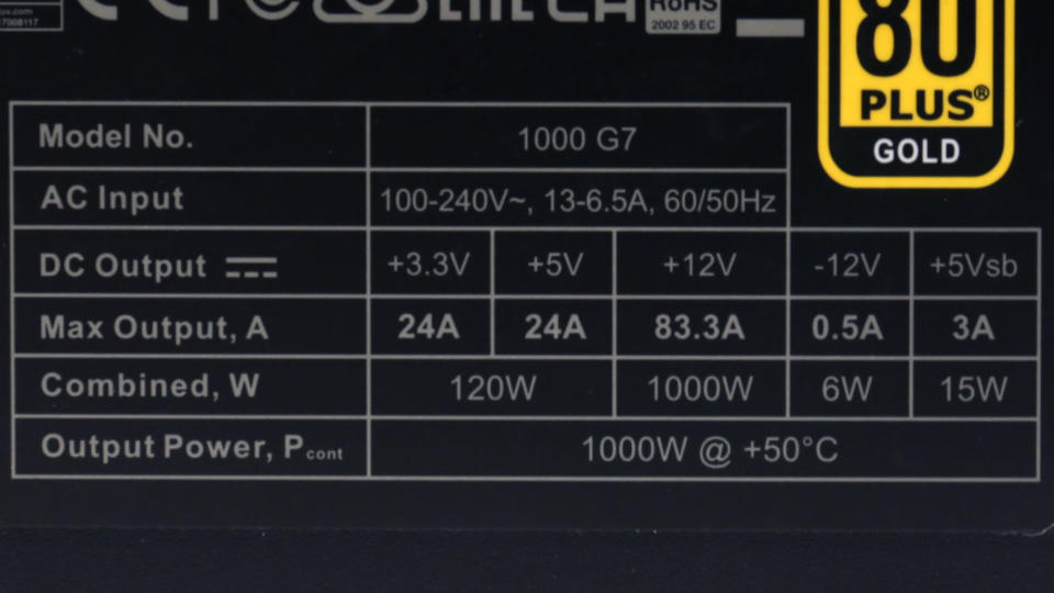
Max. DC Output | 1,000 W |
Efficiency | 80 PLUS Gold, Cybenetics Platinum (89-91%) |
Noise | Cybenetics Standard++ (30-35 dB[A]) |
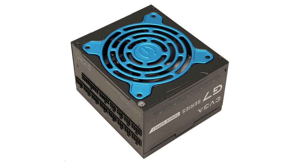
Modular | ✓(Fully) |
Intel C6/C7 Power State Support | ✓ |
Operating Temperature (Continuous Full Load) | 0 - 50°C |
Over Voltage Protection | ✓ |
Under Voltage Protection | ✓ |
Over Power Protection | ✓ |
Over Current (+12V) Protection | ✓ |
Over Temperature Protection | ✓ |
Short Circuit Protection | ✓ |
Surge Protection | ✓ |
Inrush Current Protection | ✓ |
Fan Failure Protection | ✗ |
No Load Operation | ✓ |
Cooling | 120mm Fluid Dynamic Bearing Fan (MGA12012XF-O25) |
Semi-Passive Operation | ✓(selectable) |
Dimensions (W x H x D) | 150 x 85 x 130mm |
Weight | 1.72 kg (3.79 lb) |
Form Factor | ATX12V v2.52, EPS 2.92 |
Warranty | 10 Years |
Power Specifications
Rail | 3.3V | 5V | 12V | 5VSB | -12V | |
Max. Power | Amps | 24 | 24 | 83.3 | 3 | 0.5 |
Watts | 120 | 1000 | 15 | 6 | ||
Total Max. Power (W) | 1000 |
Cables and Connectors
Description | Cable Count | Connector Count (Total) | Gauge | In Cable Capacitors |
|---|---|---|---|---|
1 | 1 | 18-22AWG | Yes | |
2 | 2 | 18AWG | No | |
3 | 6 | 18AWG | No | |
2 | 2 | 18AWG | No | |
4 | 12 | 18AWG | No | |
1 | 4 | 18AWG | No | |
1 | 1 | 22AWG | No | |
1 | 1 | 16AWG | - |
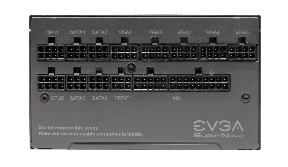
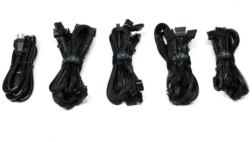
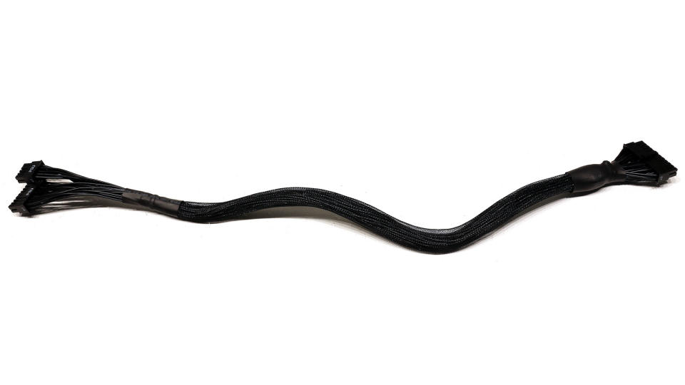
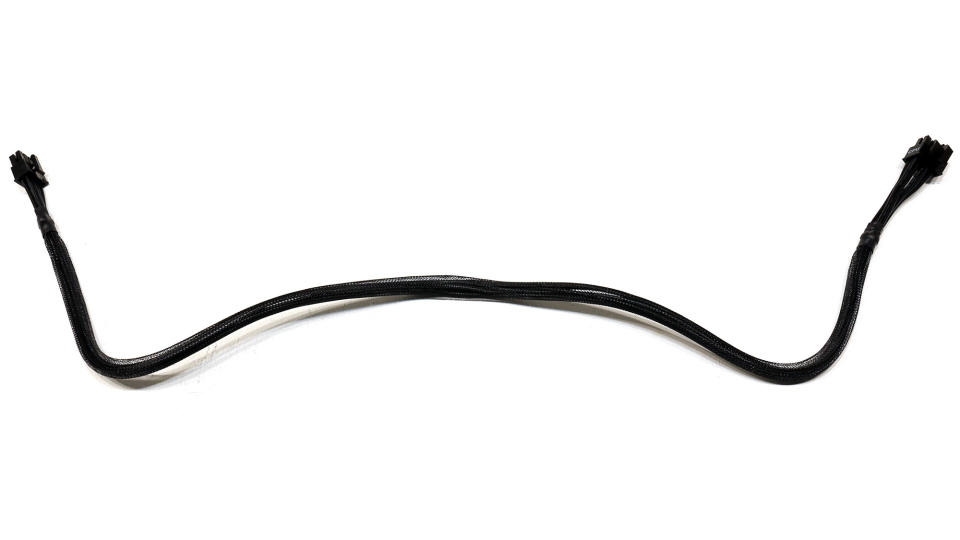
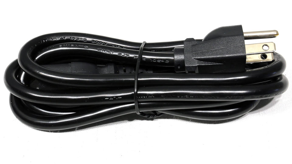
Plenty of long cables and connectors are provided, including two EPS and eight PCIe connectors. You won't find any of the new 12+4 pin PCIe connectors, though, since this PSU is not ATX 3.0 or PCIe 5.0 ready. Moreover, I would like to see a longer distance between the peripheral connectors.
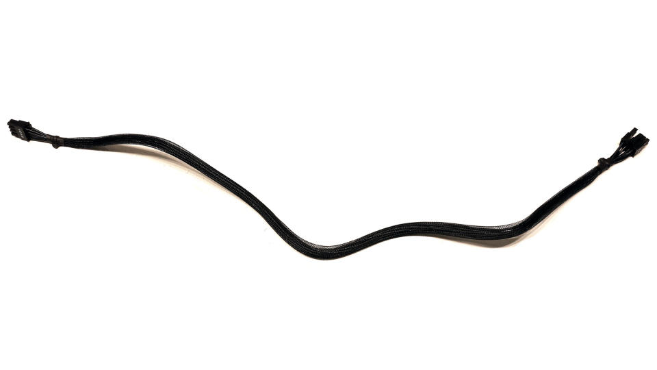
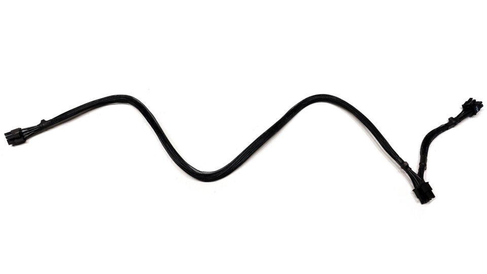
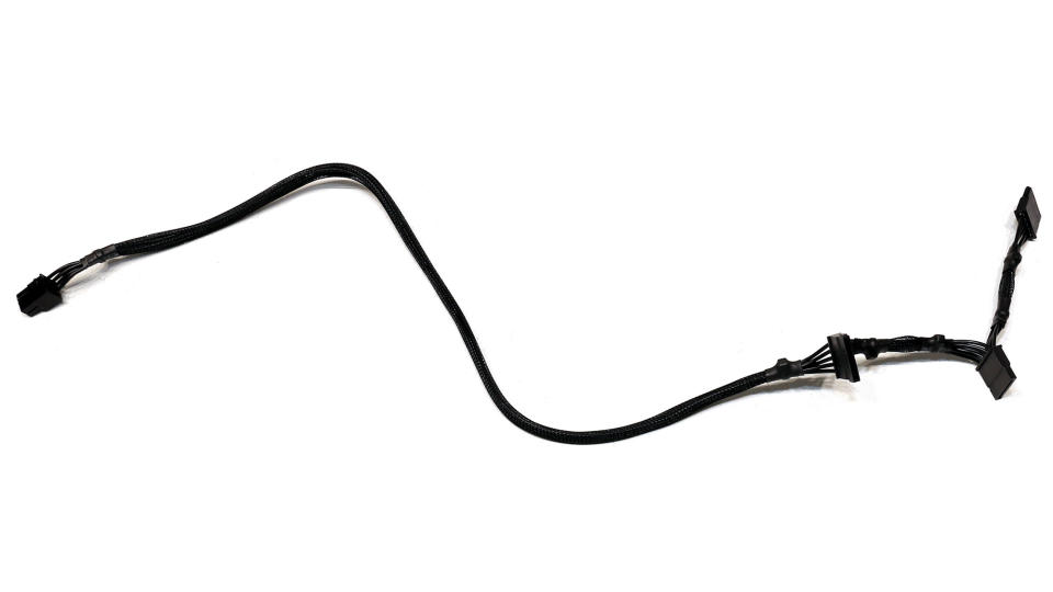
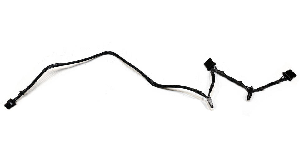
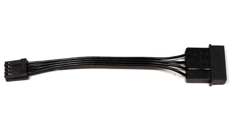
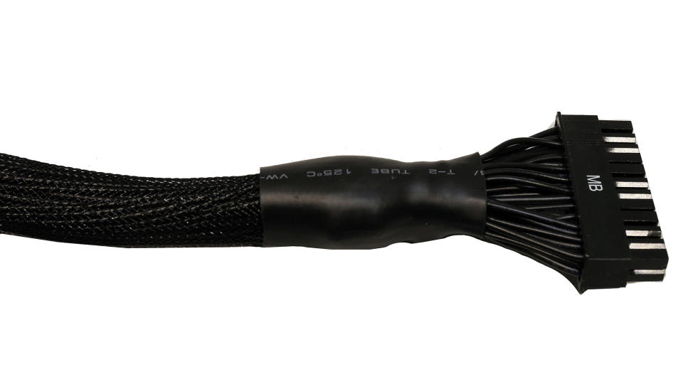
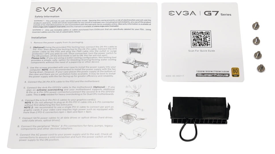
Only the ATX connector has extra caps, which are for better ripple filtering.
Component Analysis
We strongly encourage you to have a look at our PSUs 101 article, which provides valuable information about PSUs and their operation, allowing you to better understand the components we're about to discuss.
General Data | - |
Manufacturer (OEM) | FSP |
PCB Type | Double Sided |
Primary Side | - |
Transient Filter | 4x Y caps, 2x X caps, 2x CM chokes, 1x MOV |
Inrush Protection | NTC Thermistor SCK-056 (5 Ohm) & Relay |
Bridge Rectifier(s) | 2x |
APFC MOSFETs | 3x |
APFC Boost Diode | 1x |
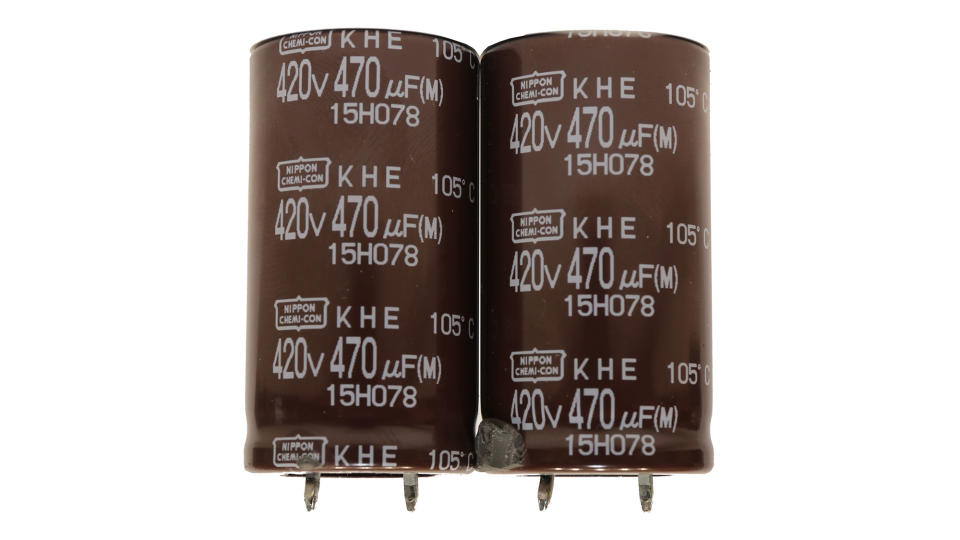
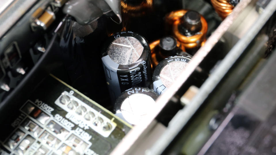
Bulk Cap(s) | 2x Nippon Chemi-Con (420V, 470uF each or 940uF combined, 2,000h @ 105°C, KHE) |
Main Switchers | 2x Infineon IPP60R120P7 (600V, 16A @ 100°C, Rds(on): 0.12Ohm) |
IC Driver | 1x Novosense NSi6602 |
APFC Controller | Infineon ICE2PCS02 |
Resonant Controller | Champion CM6901T2X |
Topology | Primary side: APFC, Half-Bridge & LLC converter |
Secondary Side | - |
+12V MOSFETs | no info |
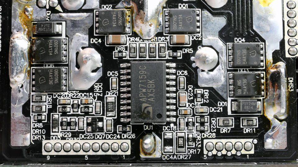
5V & 3.3V | DC-DC Converters: 6x Infineon BSC0901NS (30V, 94A @ 100°C, Rds(on): 1.9mOhm) |
Filtering Capacitors | Electrolytic: 5x Rubycon (3-6,000h @ 105°C, YXG), 3x Rubycon (1-5,000h @ 105°C, ZL) |
Supervisor IC | Weltrend WT7527RA (OCP, OVP, UVP, SCP, PG) |
Fan Controller | Microchip PICF15324 |
Fan Model | Protechnic Electric MGA12012XF-O25 (120mm, 12V, 0.52A, Fluid Dynamic Bearing Fan) |
5VSB Circuit | - |
Rectifier | 1x NIKO-SEM P1006BD (60V, 42A @ 100°C, Rds(on): 10mOhm) FET |
Standby PWM Controller | Power Integrations INN2603K |
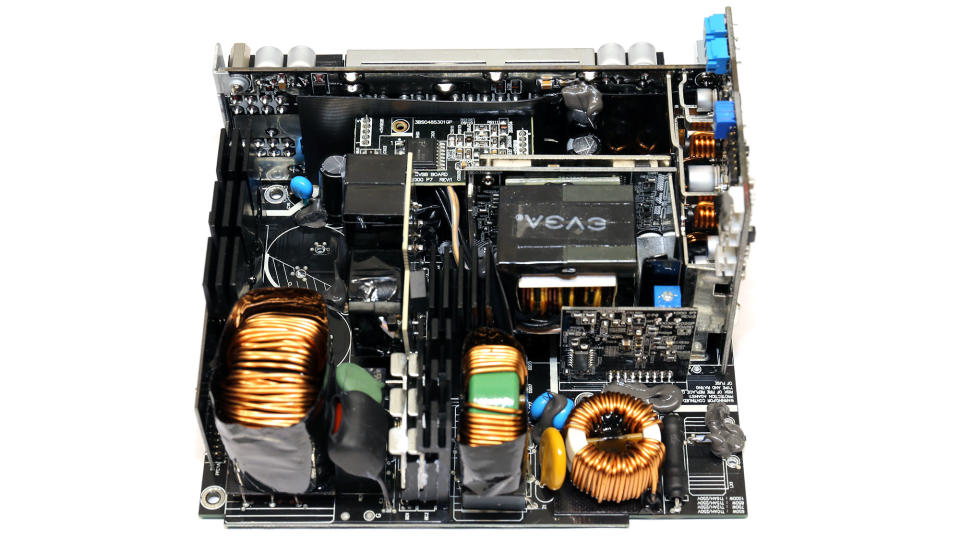
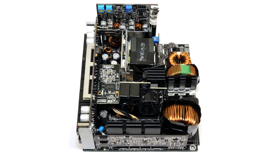
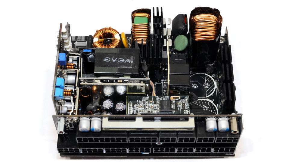
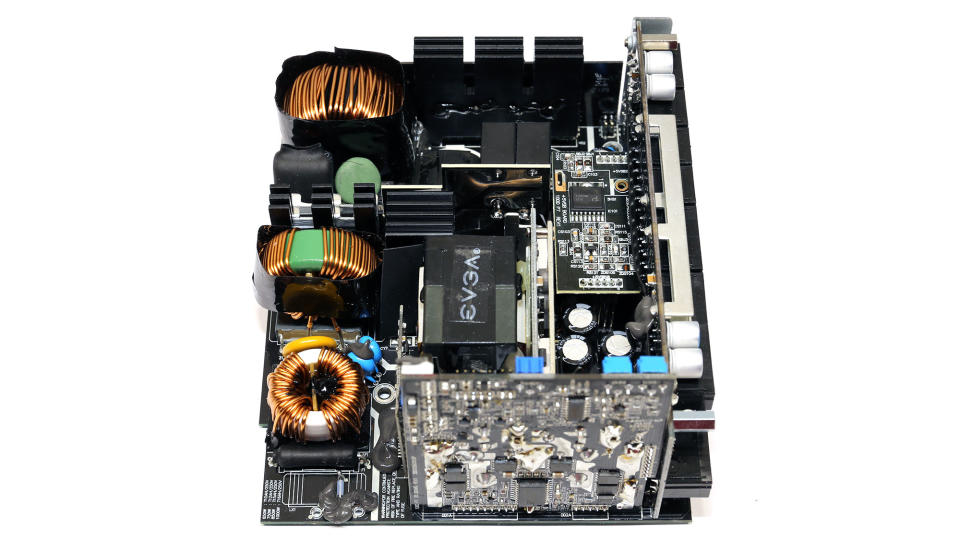
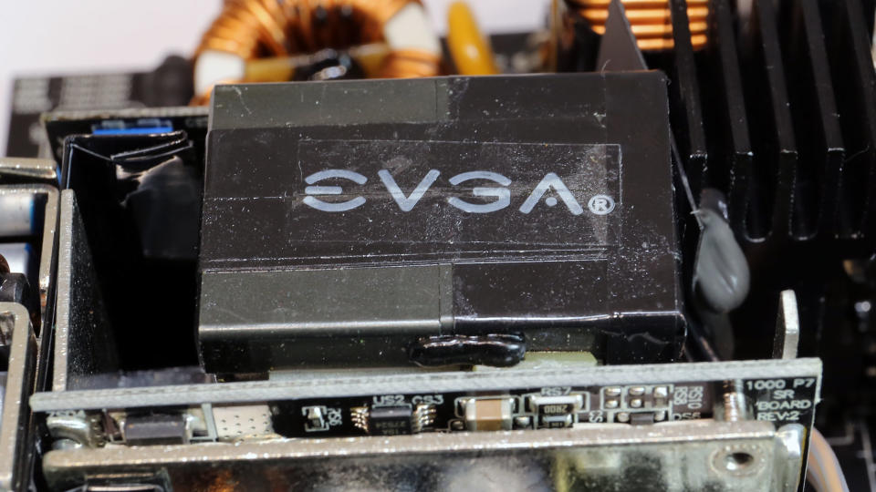
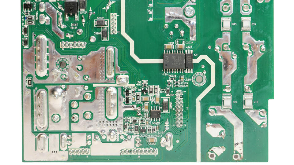
FSP makes this tiny platform. As expected, because of the high capacity, it is overpopulated, and identifying all parts without possibly destroying the PSU was pretty hard. Such PCBs always give us trouble during the part analysis process.
The design is modern with a half-bridge topology and an LLC resonant converter on the primary side. We also find a synchronous rectification scheme on the secondary side for the 12V rail and DC-DC converters for the minor rails.
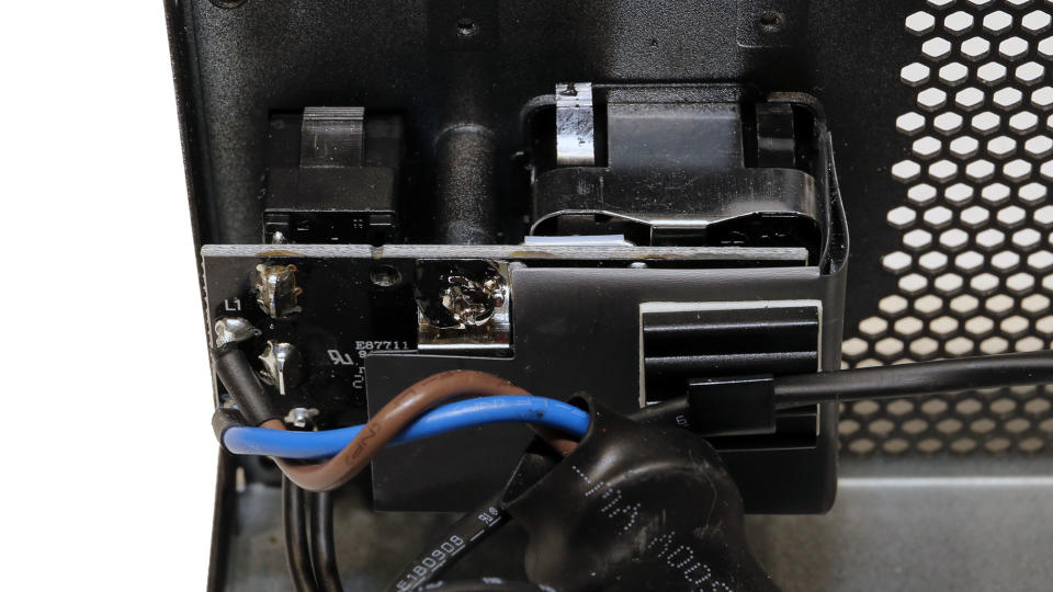
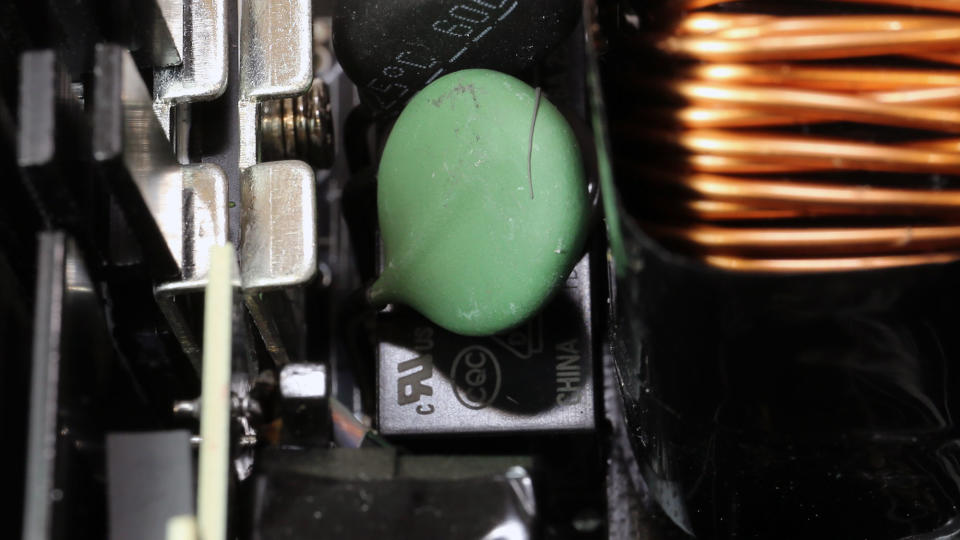
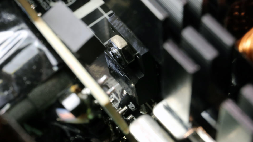
The transient/EMI filter has all the necessary parts, so I expect low EMI emissions. Moreover, it is equipped with an MOV, which handles voltage surges coming from the mains grid, and I also found an NTC thermistor and relay combo for suppressing high inrush currents.

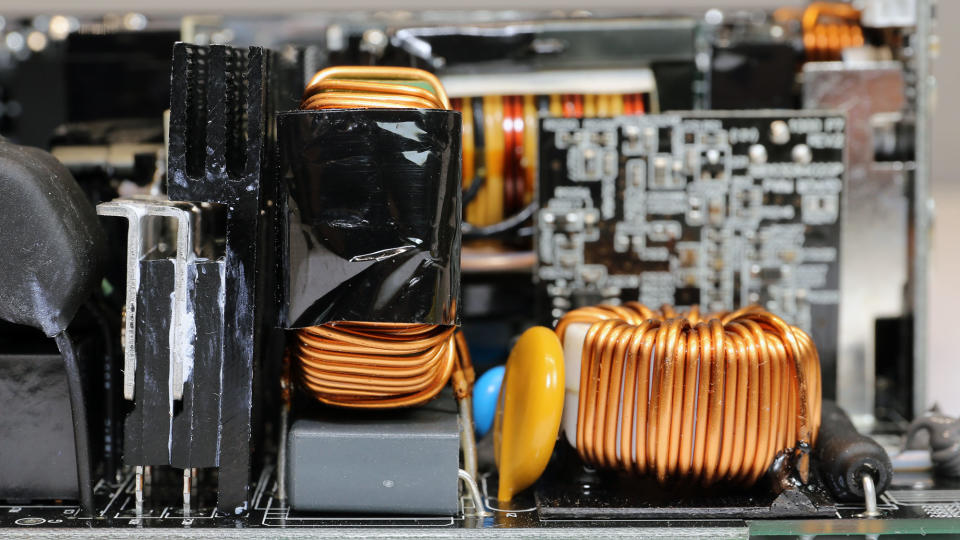
The pair of bridge rectifiers is sandwiched between two heat sinks.
The APFC converter uses three FETs and a single boost diode. The PFC controller is installed on a vertical board, an Infineon ICE2PCS02. The same board also hosts an operational amplifier (op-amp).
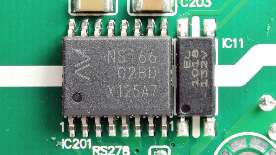
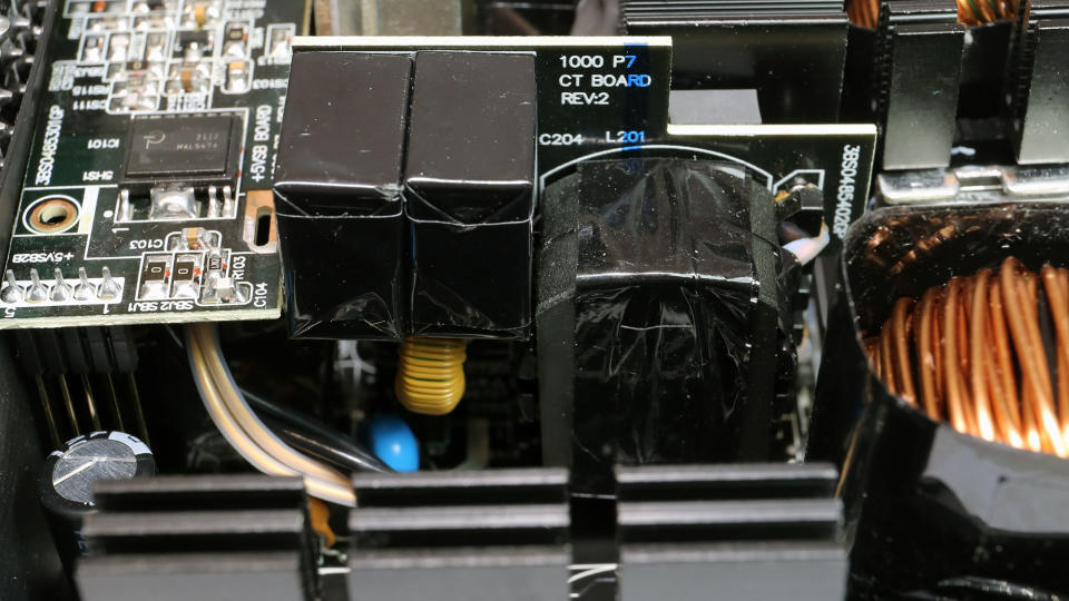
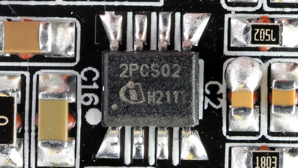
Two Infineon IPP60R120P7 are the main FETs, configured in a half-bridge topology. Their driver IC is a Novosense NSi6602, and the LLC resonant converter is the usual aspect, a Champion CM6901T2X IC. Parts of the LLC resonant converter are installed on a daughter board because there was no room on the main PCB.

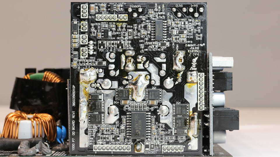
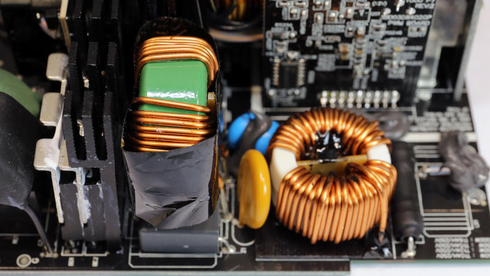
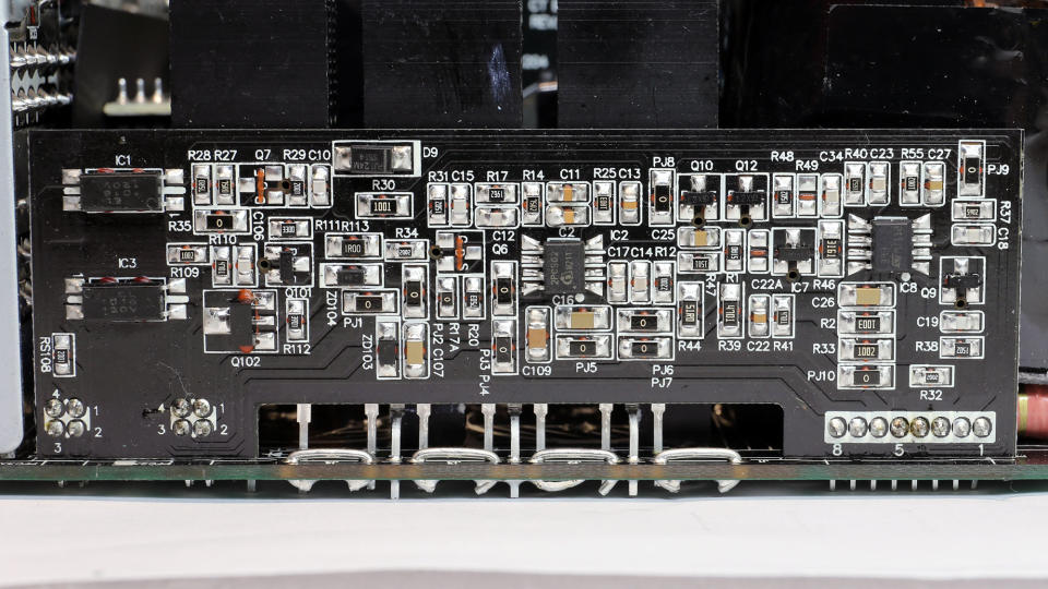
The FETs that regulate the 12V rail are installed on a board next to the main transformer to minimize energy losses. Another vertical board hosts the DC-DC converters that handle the minor rails.
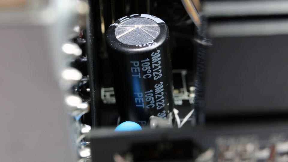
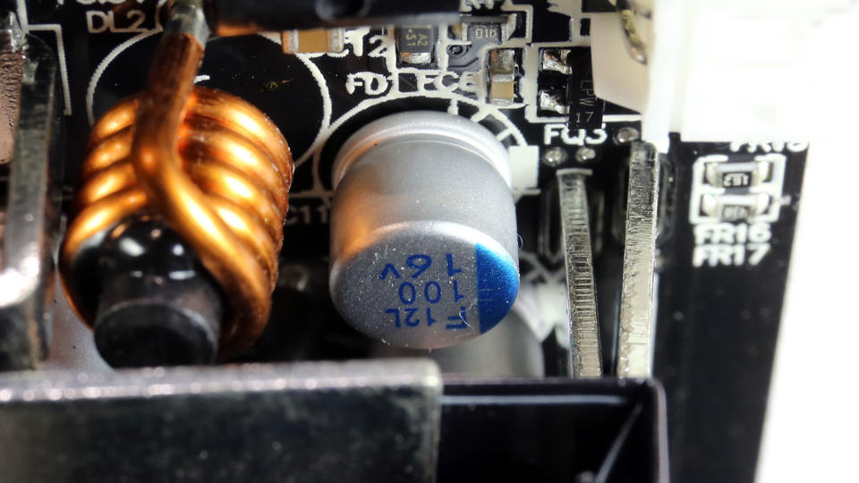
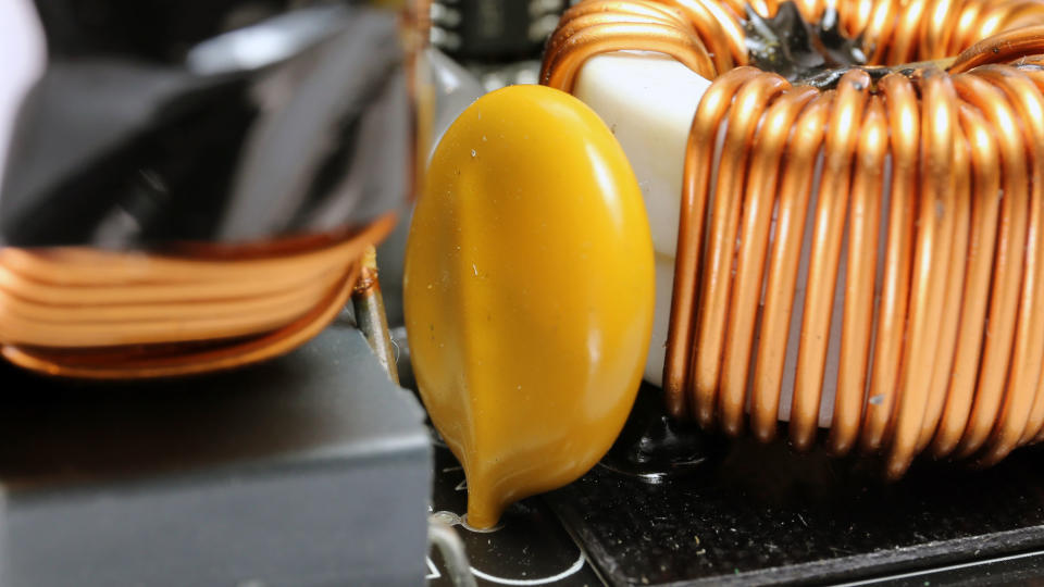
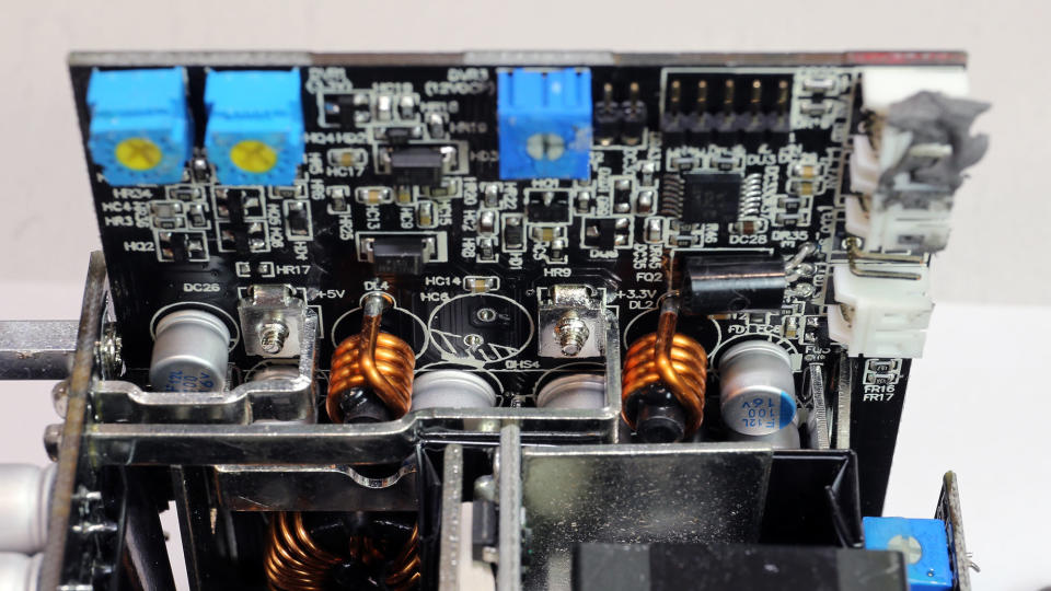
The filtering caps are high quality. On the secondary side, all electrolytic caps are by Rubycon and the polymer ones by Chemi-Con and NIC.
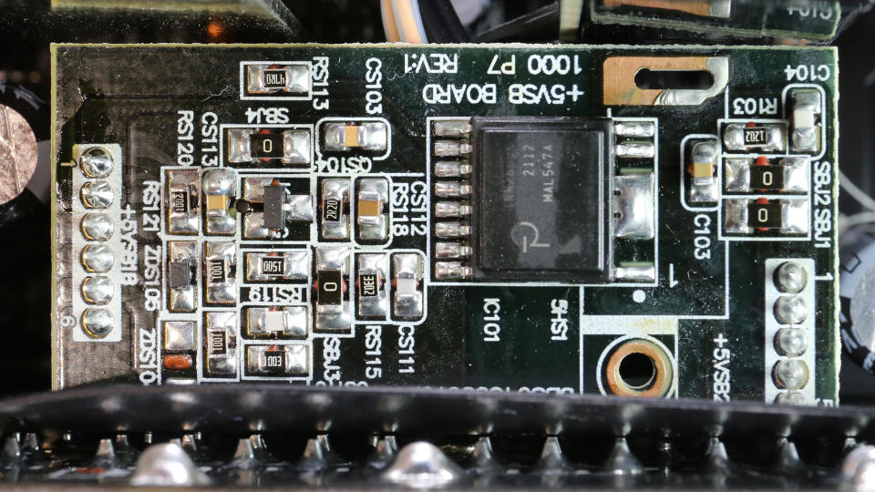

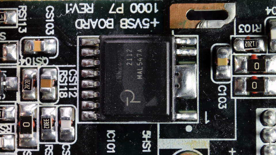
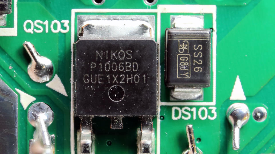
The standby PWM controller is by Power Integrations, and a NIKO-SEM P1006BD FET is the rectifier on the secondary side of the 5VSB circuit.
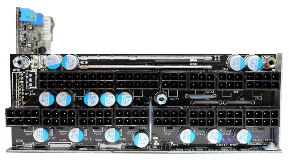
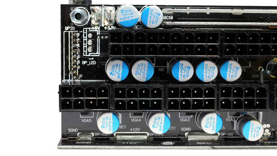
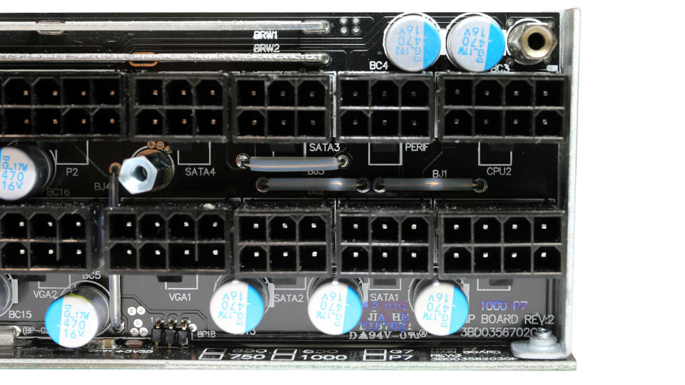
Many Chemi-Con polymer caps are installed on the modular PCB for ripple filtering purposes.
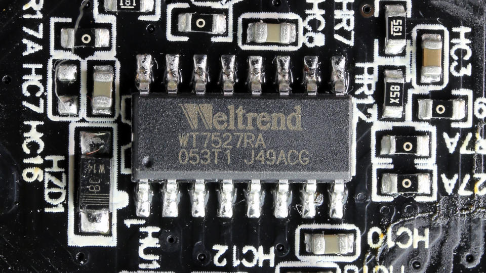
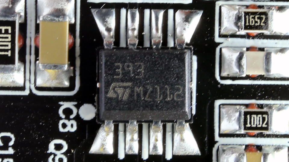
The main supervisor IC is a Weltrend WT7527RA.
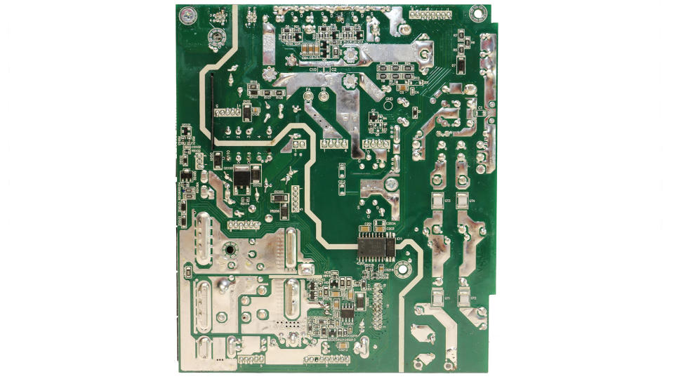
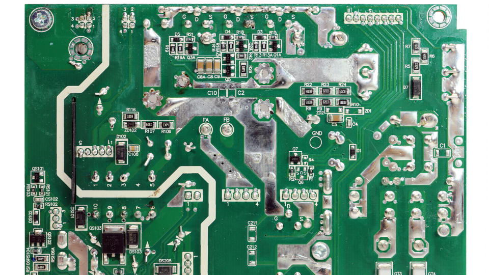
Soldering quality is good.
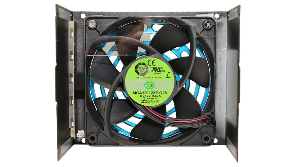
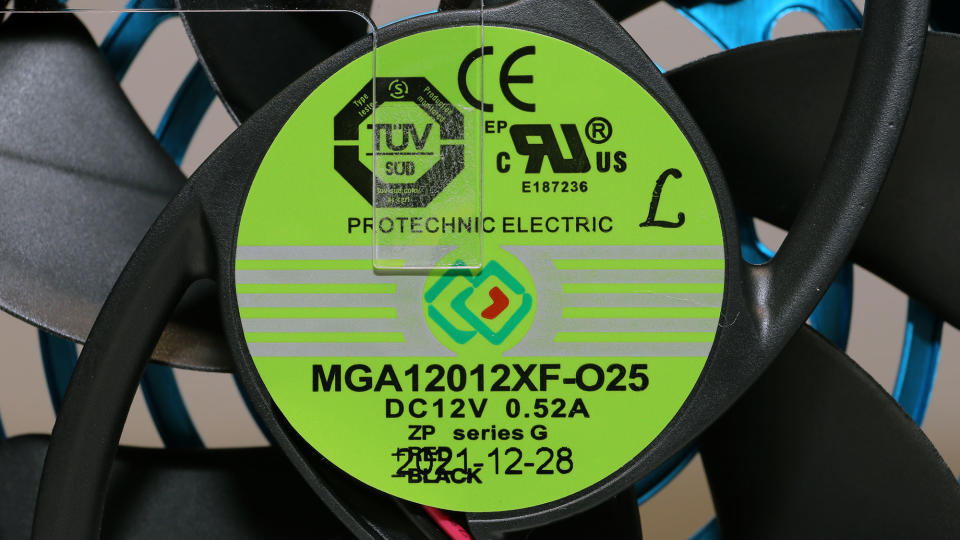
The fan is of high quality, and the fluid dynamic bearing will help it outlive the extended warranty if you don't have it operating under high operating temperatures all the time (> 40 degrees Celsius).
MORE: Best Power Supplies
MORE: How We Test Power Supplies
MORE: All Power Supply Content
To learn more about our PSU tests and methodology, please check out How We Test Power Supply Units.

Corsair RM1000x (2021)

EVGA SuperNOVA 1000 P6

Seasonic FOCUS GX-1000
Primary Rails And 5VSB Load Regulation
The following charts show the main rails' voltage values recorded between a range of 40W up to the PSU's maximum specified load, along with the deviation (in percent). Tight regulation is an important consideration every time we review a power supply because it facilitates constant voltage levels despite varying loads. Tight load regulation also, among other factors, improves the system’s stability, especially under overclocked conditions and, at the same time, it applies less stress to the DC-DC converters that many system components utilize.
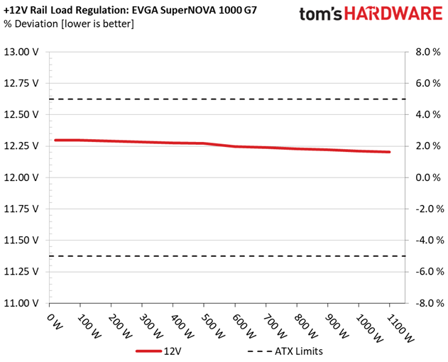
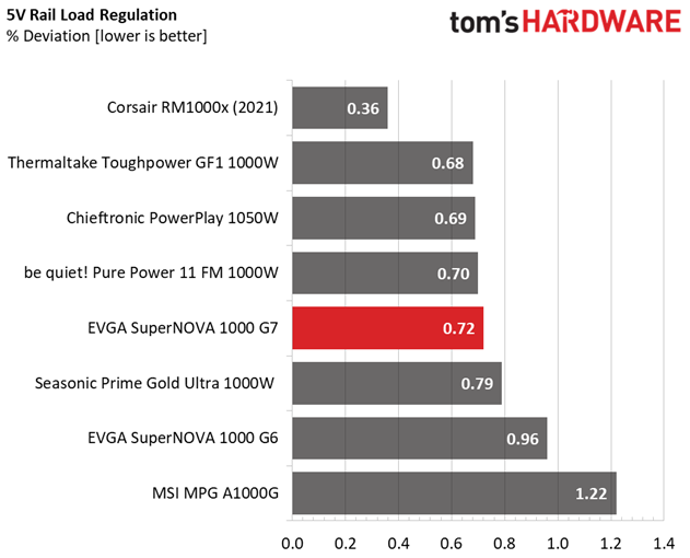
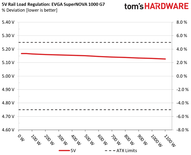
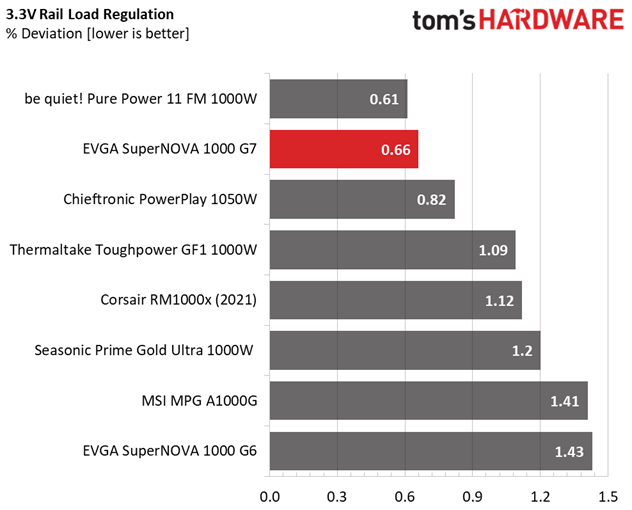


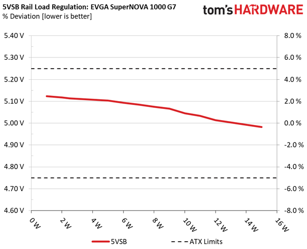
Load regulation is tight enough on all rails.
Hold-Up Time
Put simply; hold-up time is the amount of time that the system can continue to run without shutting down or rebooting during a power interruption.
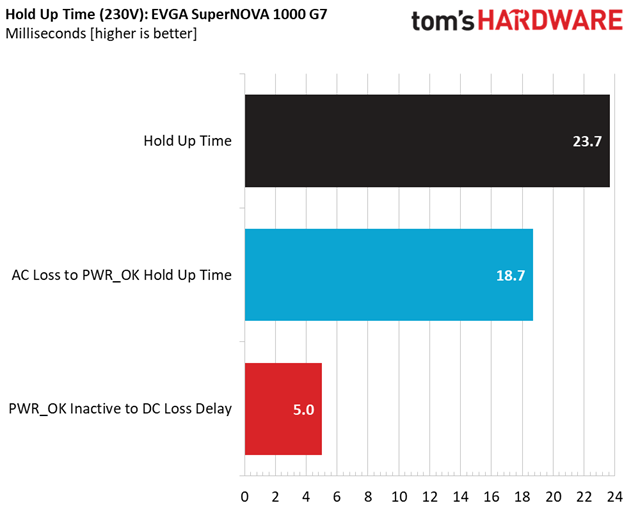
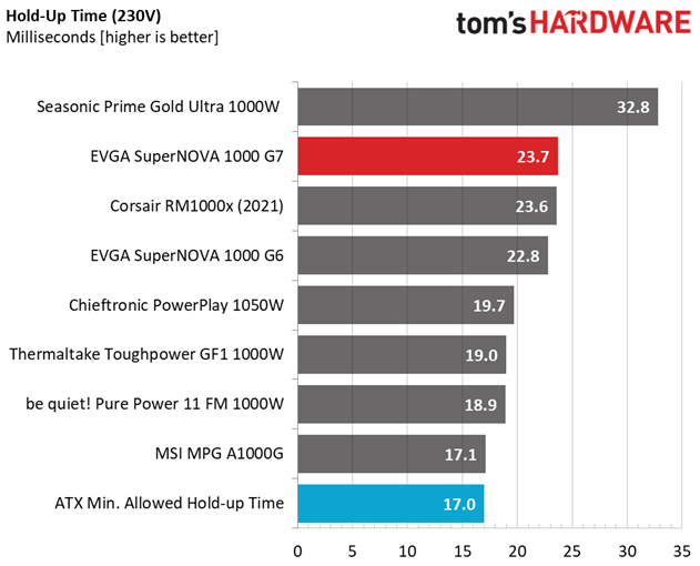
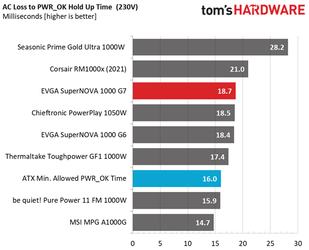
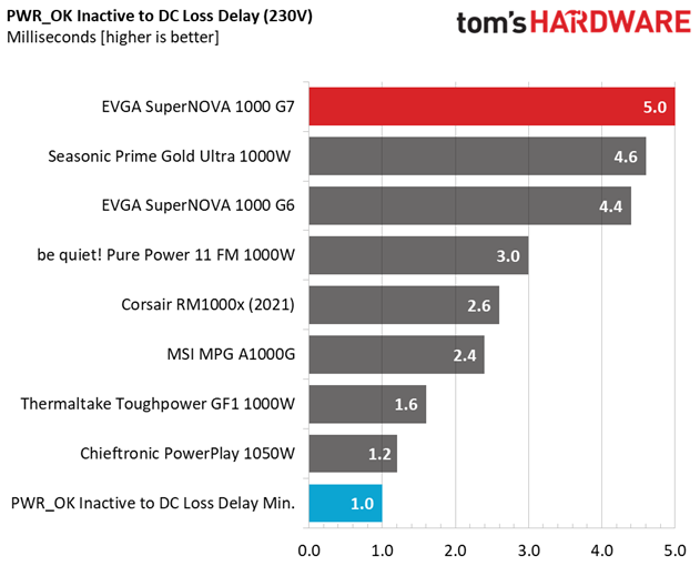
The hold-up time is long and the power ok signal is accurate.
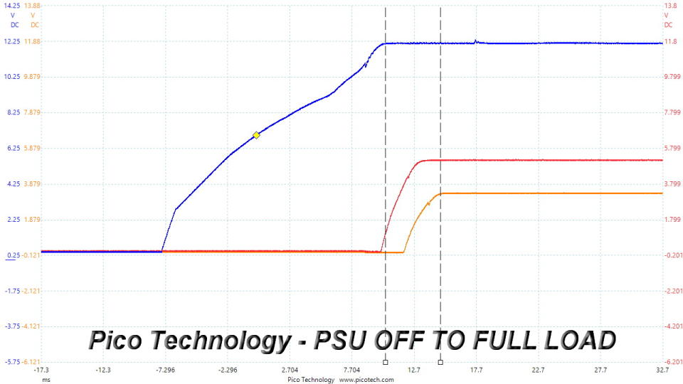
Inrush Current
Inrush current, or switch-on surge, refers to the maximum, instantaneous input current drawn by an electrical device when it is first turned on. A large enough inrush current can cause circuit breakers and fuses to trip. It can also damage switches, relays, and bridge rectifiers. As a result, the lower the inrush current of a PSU right as it is turned on, the better.
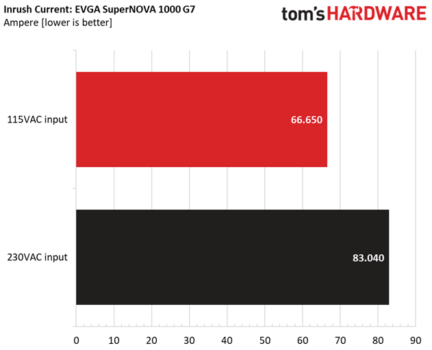
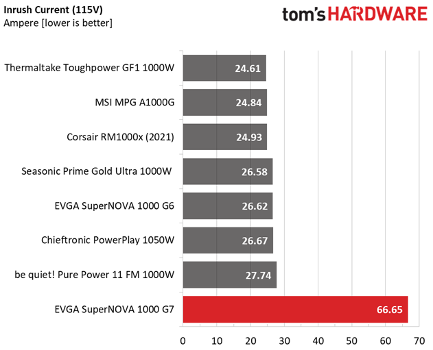
Inrush current is high with both voltage inputs that we tried.
Leakage Current
In layman's terms, leakage current is the unwanted transfer of energy from one circuit to another. In power supplies, it is the current flowing from the primary side to the ground or the chassis, which in the majority of cases is connected to the ground. For measuring leakage current, we use a GW Instek GPT-9904 electrical safety tester instrument.
The leakage current test is conducted at 110% of the DUT's rated voltage input (so for a 230-240V device, we should conduct the test with 253-264V input). The maximum acceptable limit of a leakage current is 3.5 mA and it is defined by the IEC-60950-1 regulation, ensuring that the current is low and will not harm any person coming in contact with the power supply's chassis.
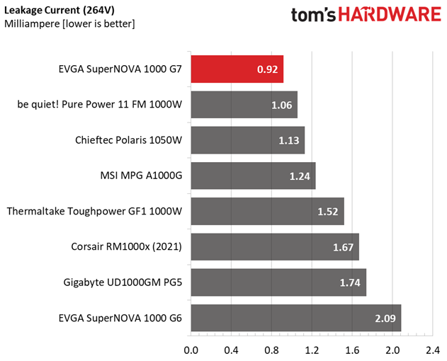
Leakage current is low.
10-110% Load Tests
These tests reveal the PSU's load regulation and efficiency levels under high ambient temperatures. They also show how the fan speed profile behaves under increased operating temperatures.
Test | 12V | 5V | 3.3V | 5VSB | DC/AC (Watts) | Efficiency | Fan Speed (RPM) | PSU Noise (dB[A]) | Temps (In/Out) | PF/AC Volts |
10% | 6.374A | 1.936A | 1.958A | 0.98A | 99.987 | 88.011% | 0 | <6.0 | 44.64°C | 0.971 |
12.298V | 5.165V | 3.371V | 5.103V | 113.606 | 40.33°C | 115.14V | ||||
20% | 13.754A | 2.907A | 2.939A | 1.178A | 199.926 | 91.314% | 0 | <6.0 | 45.75°C | 0.991 |
12.290V | 5.16V | 3.368V | 5.094V | 218.946 | 40.95°C | 115.11V | ||||
30% | 21.487A | 3.394A | 3.43A | 1.377A | 299.965 | 92.273% | 0 | <6.0 | 46.35°C | 0.994 |
12.282V | 5.157V | 3.367V | 5.085V | 325.085 | 41.23°C | 115.08V | ||||
40% | 29.184A | 3.88A | 3.922A | 1.576A | 399.492 | 92.427% | 0 | <6.0 | 47.75°C | 0.995 |
12.277V | 5.154V | 3.366V | 5.075V | 432.222 | 42.12°C | 115.05V | ||||
50% | 36.559A | 4.853A | 4.903A | 1.777A | 499.227 | 92.164% | 0 | <6.0 | 49.13°C | 0.995 |
12.274V | 5.152V | 3.365V | 5.066V | 541.676 | 43.02°C | 115.02V | ||||
60% | 44.092A | 5.831A | 5.895A | 1.982A | 599.759 | 91.601% | 1236 | 30.2 | 43.16°C | 0.996 |
12.246V | 5.146V | 3.359V | 5.045V | 654.748 | 49.87°C | 114.98V | ||||
70% | 51.496A | 6.808A | 6.882A | 2.184A | 699.465 | 91.089% | 1405 | 34.7 | 43.43°C | 0.995 |
12.241V | 5.142V | 3.357V | 5.034V | 767.891 | 50.58°C | 114.95V | ||||
80% | 59.004A | 7.787A | 7.868A | 2.288A | 799.488 | 90.442% | 1717 | 39.8 | 43.73°C | 0.995 |
12.229V | 5.138V | 3.354V | 5.024V | 883.981 | 51.78°C | 114.91V | ||||
90% | 66.840A | 8.276A | 8.351A | 2.392A | 899.243 | 89.713% | 2040 | 44.7 | 44.56°C | 0.994 |
12.221V | 5.134V | 3.352V | 5.014V | 1002.344 | 53.66°C | 114.87V | ||||
100% | 74.494A | 8.769A | 8.864A | 3.005A | 999.212 | 88.953% | 2343 | 47.5 | 46.24°C | 0.994 |
12.210V | 5.131V | 3.35V | 4.99V | 1123.303 | 56.37°C | 114.84V | ||||
110% | 82.078A | 9.752A | 9.946A | 3.009A | 1099.856 | 87.97% | 2683 | 50.8 | 46.55°C | 0.994 |
12.203V | 5.127V | 3.347V | 4.983V | 1250.246 | 57.43°C | 114.8V | ||||
CL1 | 0.112A | 14.013A | 14.163A | 0A | 121.278 | 85.802% | 0 | <6.0 | 47.97°C | 0.98 |
12.308V | 5.152V | 3.367V | 5.119V | 141.341 | 42.83°C | 115.13V | ||||
CL2 | 0.112A | 23.299A | 0A | 0A | 121.381 | 84.245% | 0 | <6.0 | 49.51°C | 0.981 |
12.308V | 5.151V | 3.368V | 5.124V | 144.075 | 43.12°C | 115.13V | ||||
CL3 | 0.112A | 0A | 23.45A | 0A | 80.57 | 79.28% | 0 | <6.0 | 51.83°C | 0.967 |
12.299V | 5.164V | 3.377V | 5.114V | 101.638 | 44.64°C | 115.14V | ||||
CL4 | 81.835A | 0A | 0A | 0A | 999.846 | 89.444% | 2277 | 47.5 | 45.19°C | 0.994 |
12.218V | 5.144V | 3.358V | 5.073V | 1117.842 | 55.16°C | 114.85V |
The PSU doesn't have a problem operating under high temperatures for prolonged periods, but you should expect high noise output.
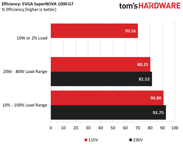
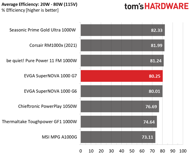
20-80W Load Tests
In the following tests, we measure the PSU's efficiency at loads significantly lower than 10% of its maximum capacity (the lowest load the 80 PLUS standard measures). This is important for representing when a PC is idle with power-saving features turned on.
Test | 12V | 5V | 3.3V | 5VSB | DC/AC (Watts) | Efficiency | Fan Speed (RPM) | PSU Noise (dB[A]) | Temps (In/Out) | PF/AC Volts |
20W | 1.207A | 0.484A | 0.489A | 0.195A | 19.99 | 69.134% | 0 | <6.0 | 40.23°C | 0.788 |
12.299V | 5.168V | 3.372V | 5.123V | 28.913 | 37.15°C | 115.17V | ||||
40W | 2.657A | 0.677A | 0.685A | 0.293A | 39.99 | 80.216% | 0 | <6.0 | 41.24°C | 0.9 |
12.299V | 5.167V | 3.372V | 5.12V | 49.851 | 37.87°C | 115.16V | ||||
60W | 4.108A | 0.871A | 0.881A | 0.391A | 59.989 | 84.662% | 0 | <6.0 | 41.61°C | 0.941 |
12.298V | 5.167V | 3.372V | 5.117V | 70.856 | 37.86°C | 115.15V | ||||
80W | 5.554A | 1.064A | 1.076A | 0.489A | 79.935 | 86.967% | 0 | <6.0 | 43.76°C | 0.96 |
12.298V | 5.166V | 3.372V | 5.114V | 91.915 | 39.79°C | 115.15V |
The unit achieves high efficiency under light loads, with minimal noise output because the fan doesn't spin.
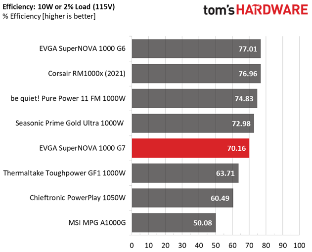
2% or 10W Load Test
From July 2020, the ATX spec requires 70% and higher efficiency with 115V input. The applied load is only 10W for PSUs with 500W and lower capacities, while for stronger units, we dial 2% of their max-rated capacity.
12V | 5V | 3.3V | 5VSB | DC/AC (Watts) | Efficiency | Fan Speed (RPM) | PSU Noise (dB[A]) | Temps (In/Out) | PF/AC Volts |
1.472A | 0.255A | 0.255A | 0.053A | 20.545 | 70.164% | 0 | <6.0 | 35.04°C | 0.792 |
12.298V | 5.167V | 3.371V | 5.128V | 29.282 | 23.65°C | 115.16V |
The PSU achieves over 70% efficiency with a 2% load, as the ATX spec recommends.
Efficiency & Power Factor
Next, we plotted a chart showing the PSU's efficiency at low loads and loads from 10 to 110% of its maximum rated capacity. The higher a PSU’s efficiency, the less energy goes wasted, leading to a reduced carbon footprint and lower electricity bills. The same goes for Power Factor.
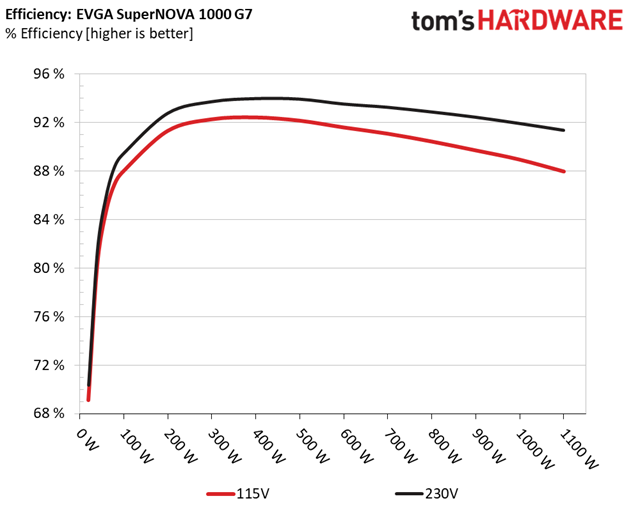
This is a highly efficient platform. There is room for improvement, though, at super-light loads.
5VSB Efficiency
Test # | 5VSB | DC/AC (Watts) | Efficiency | PF/AC Volts |
1 | 0.1A | 0.512W | 76.602% | 0.064 |
5.124V | 0.668W | 115.16V | ||
2 | 0.25A | 1.28W | 80.835% | 0.142 |
5.123V | 1.584W | 115.16V | ||
3 | 0.55A | 2.813W | 81.626% | 0.26 |
5.115V | 3.446W | 115.16V | ||
4 | 1A | 5.107W | 79.616% | 0.357 |
5.107V | 6.415W | 115.16V | ||
5 | 1.5A | 7.644W | 79.448% | 0.412 |
5.096V | 9.622W | 115.16V | ||
6 | 2.999A | 15.16W | 78.969% | 0.477 |
5.055V | 19.198W | 115.16V |
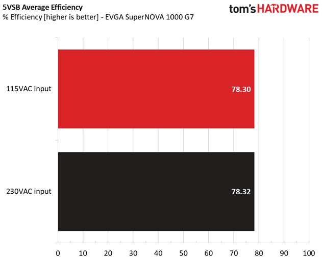
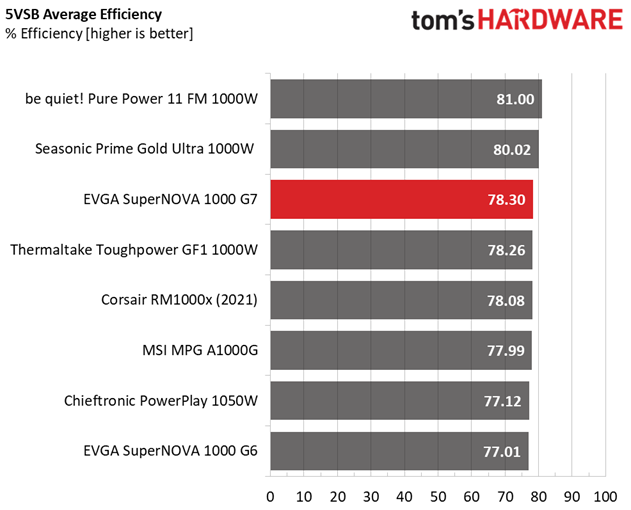
The 5VSB rail is efficient.
Power Consumption In Idle And Standby
Mode | 12V | 5V | 3.3V | 5VSB | Watts | PF/AC Volts |
Idle | 12.278V | 5.162V | 3.363V | 5.122V | 7.955 | 0.42 |
115.16V | ||||||
Standby | 0.058 | 0.006 | ||||
115.16V |
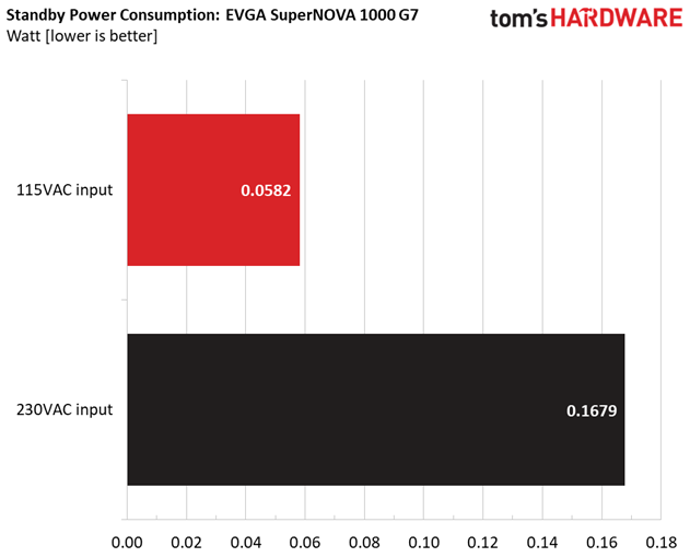
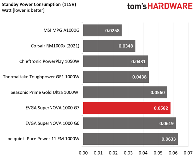
We would like to see below 0.1W vampire power with 230V input.
Fan RPM, Delta Temperature, And Output Noise
All results are obtained between an ambient temperature of 37 to 47 degrees Celsius (98.6 to 116.6 degrees Fahrenheit).
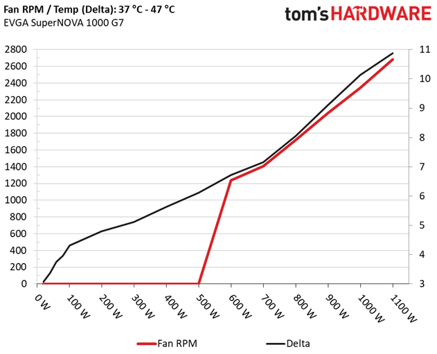
The fan's speed increases linearly as the load and the operating temperatures increase. Given the small and overpopulated PCB and the high Wattage, this is the best FSP could do, also considering the ten-year warranty.
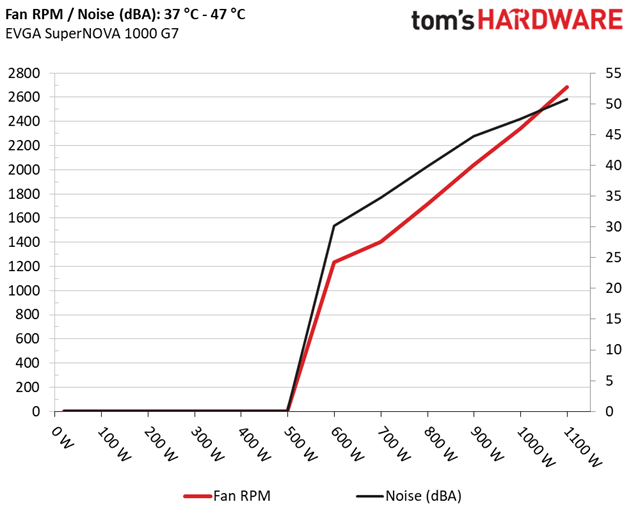
The following results were obtained at 30 to 32 degrees Celsius (86 to 89.6 degrees Fahrenheit) ambient temperature.
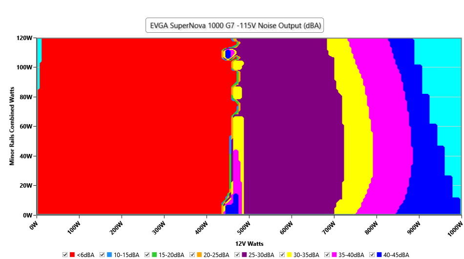
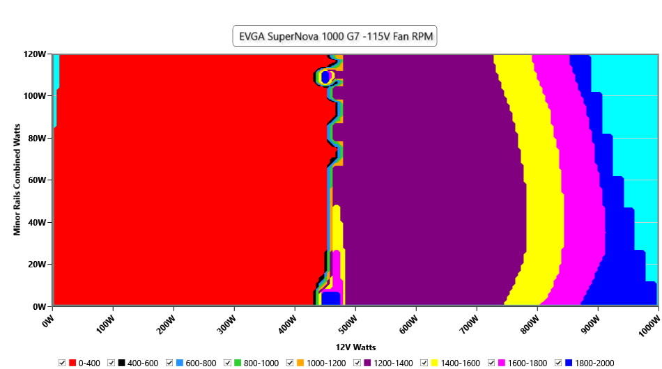
At normal operating temperatures, close to 30 degrees Celsius, the PSU's passive mode lasts for long, and the load on the minor rails doesn't seem to affect it. The 30 dBA mark is passed with 700 W and, with above 850 W, noise exceeds 40 dBA.
MORE: Best Power Supplies
MORE: How We Test Power Supplies
MORE: All Power Supply Content
Protection Features
Check out our PSUs 101 article to learn more about PSU protection features.
OCP (Cold @ 25°C) | 12V: 99A (118.84%), 12.170V |
OCP (Hot @ 41°C) | 12V: 97.2A (116.67%), 12.195V |
OPP (Cold @ 24°C) | 1291.64W (129.16%) |
OPP (Hot @ 44°C) | 1258.75W (125.88%) |
OTP | ✓ (156°C @ 12V Secondary Side) |
SCP | 12V to Earth: ✓ |
PWR_OK | Proper Operation |
NLO | ✓ |
SIP | Surge: MOV |
OCP and OPP are set correctly. Lastly, the other protection features are present and work properly.
DC Power Sequencing
According to Intel’s most recent Power Supply Design Guide (revision 1.4), the +12V and 5V outputs must be equal to or greater than the 3.3V rail at all times. Unfortunately, Intel doesn't mention why it is so important to always keep the 3.3V rail's voltage lower than the levels of the other two outputs.
No problems here since the 3.3V rail is always lower than the other two.
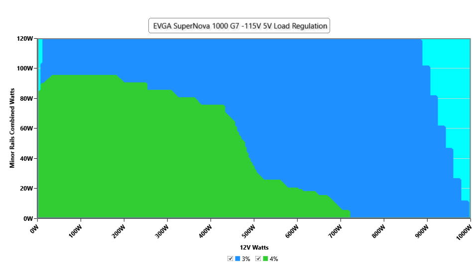
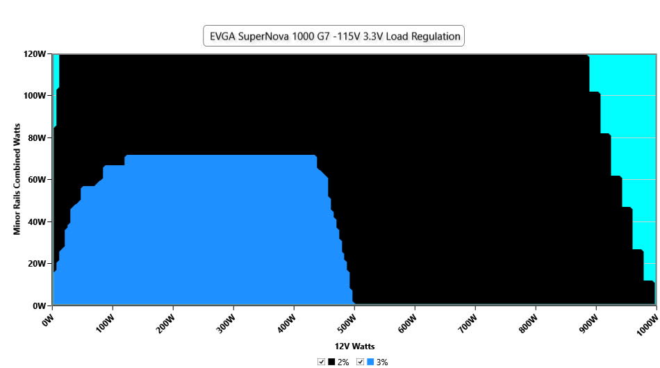
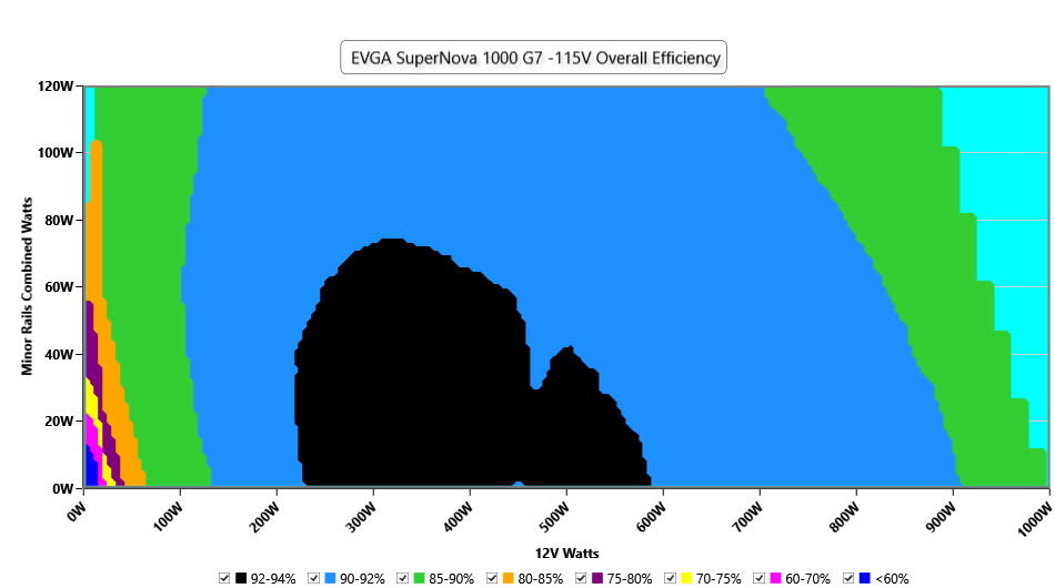
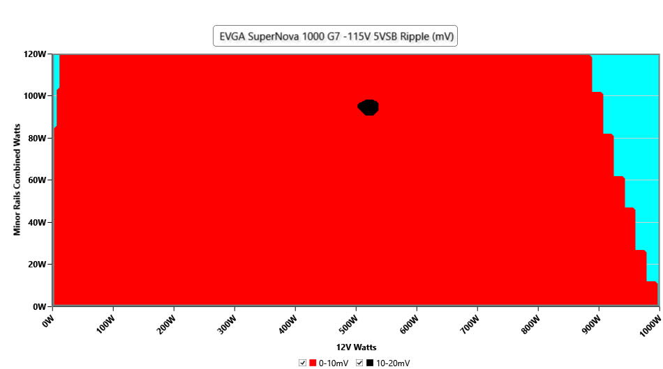
Cross Load Tests
To generate the following charts, we set our loaders to auto mode through custom-made software before trying more than 25,000 possible load combinations with the +12V, 5V, and 3.3V rails. The deviations in each of the charts below are calculated by taking the nominal values of the rails (12V, 5V, and 3.3V) as point zero. The ambient temperature during testing was between 30 to 32 degrees Celsius (86 to 89.6 degrees Fahrenheit).
Load Regulation Charts
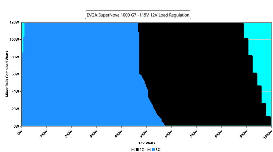
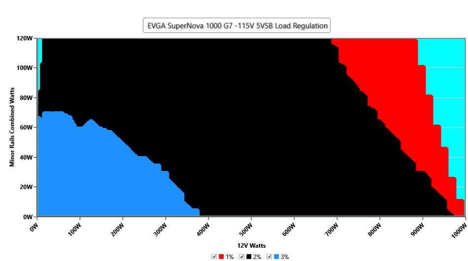
Efficiency Graph
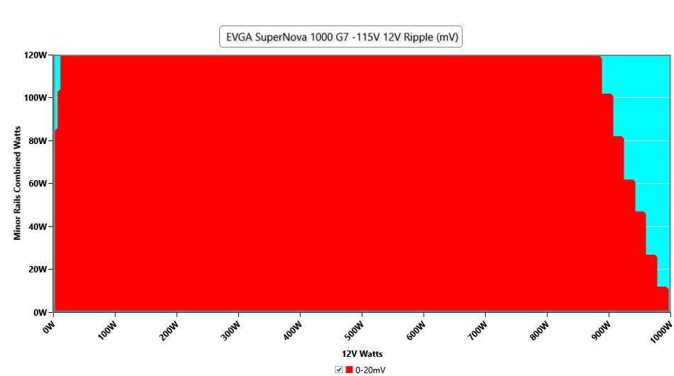
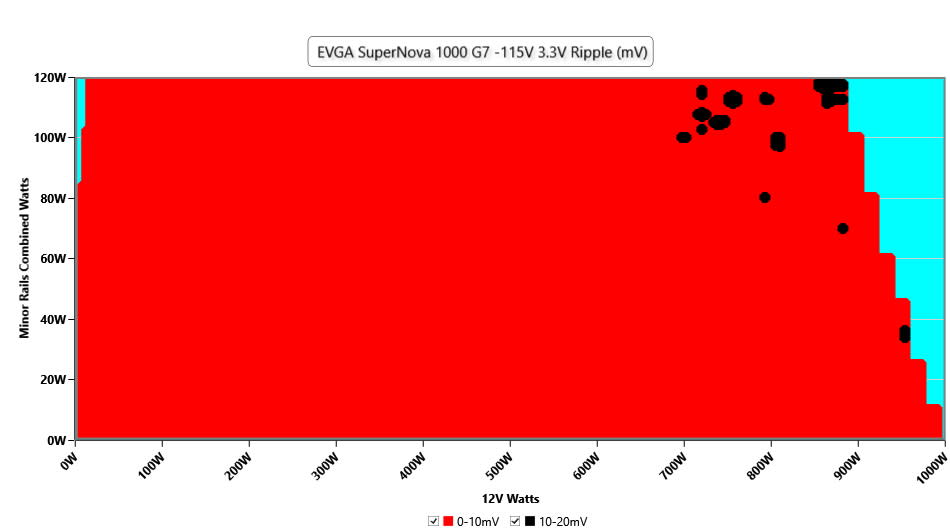
Ripple Graphs
The lower the power supply's ripple, the more stable the system will be and less stress will also be applied to its components.

Infrared Images
We apply a half-load for 10 minutes with the PSU's top cover and cooling fan removed before taking photos with a modified Fluke Ti480 PRO camera able to deliver an IR resolution of 640x480 (307,200 pixels).
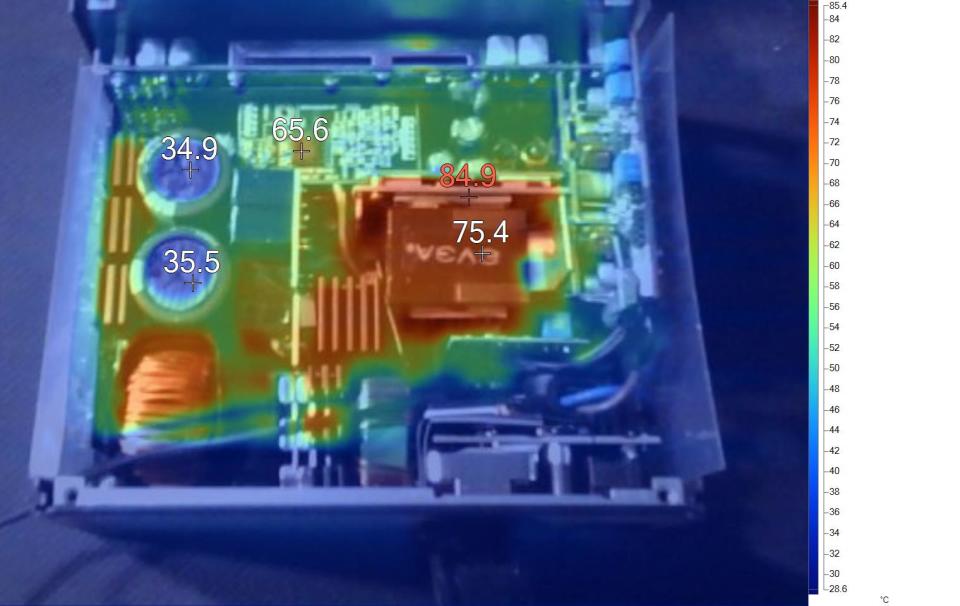
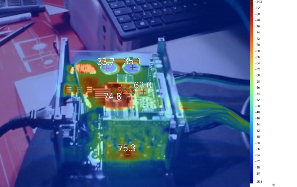
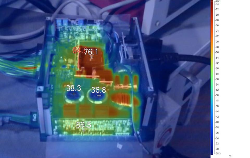
The main transformer and the vertical board holding the 12V FETs are the hottest parts. All in all, the temperatures on all parts are kept in control during this test.
MORE: Best Power Supplies
MORE: How We Test Power Supplies
MORE: All Power Supply Content
Advanced Transient Response Tests
For details about our transient response testing, please click here.
In the real world, power supplies are always working with loads that change. It's of immense importance, then, for the PSU to keep its rails within the ATX specification's defined ranges. The smaller the deviations, the more stable your PC will be with less stress applied to its components.
We should note that the ATX spec requires capacitive loading during the transient rests, but in our methodology, we also choose to apply a worst case scenario with no additional capacitance on the rails.
Advanced Transient Response at 20% – 20ms
Voltage | Before | After | Change | Pass/Fail |
12V | 12.275V | 12.182V | 0.75% | Pass |
5V | 5.158V | 5.056V | 1.99% | Pass |
3.3V | 3.366V | 3.255V | 3.30% | Pass |
5VSB | 5.085V | 5.063V | 0.44% | Pass |
Advanced Transient Response at 20% – 10ms
Voltage | Before | After | Change | Pass/Fail |
12V | 12.275V | 12.186V | 0.73% | Pass |
5V | 5.158V | 5.056V | 1.98% | Pass |
3.3V | 3.366V | 3.255V | 3.29% | Pass |
5VSB | 5.086V | 5.066V | 0.38% | Pass |
Advanced Transient Response at 20% – 1ms
Voltage | Before | After | Change | Pass/Fail |
12V | 12.278V | 12.206V | 0.59% | Pass |
5V | 5.158V | 5.060V | 1.89% | Pass |
3.3V | 3.366V | 3.251V | 3.42% | Pass |
5VSB | 5.086V | 5.070V | 0.32% | Pass |
Advanced Transient Response at 50% – 20ms
Voltage | Before | After | Change | Pass/Fail |
12V | 12.250V | 12.179V | 0.58% | Pass |
5V | 5.147V | 5.048V | 1.93% | Pass |
3.3V | 3.359V | 3.246V | 3.37% | Pass |
5VSB | 5.052V | 5.033V | 0.37% | Pass |
Advanced Transient Response at 50% – 10ms
Voltage | Before | After | Change | Pass/Fail |
12V | 12.250V | 12.171V | 0.64% | Pass |
5V | 5.147V | 5.045V | 1.99% | Pass |
3.3V | 3.359V | 3.248V | 3.31% | Pass |
5VSB | 5.052V | 5.034V | 0.37% | Pass |
Advanced Transient Response at 50% – 1ms
Voltage | Before | After | Change | Pass/Fail |
12V | 12.253V | 12.178V | 0.61% | Pass |
5V | 5.148V | 5.048V | 1.94% | Pass |
3.3V | 3.360V | 3.244V | 3.46% | Pass |
5VSB | 5.054V | 5.032V | 0.43% | Pass |
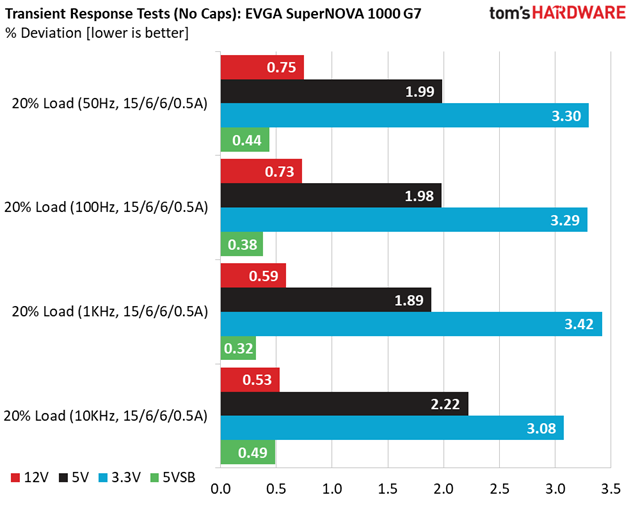
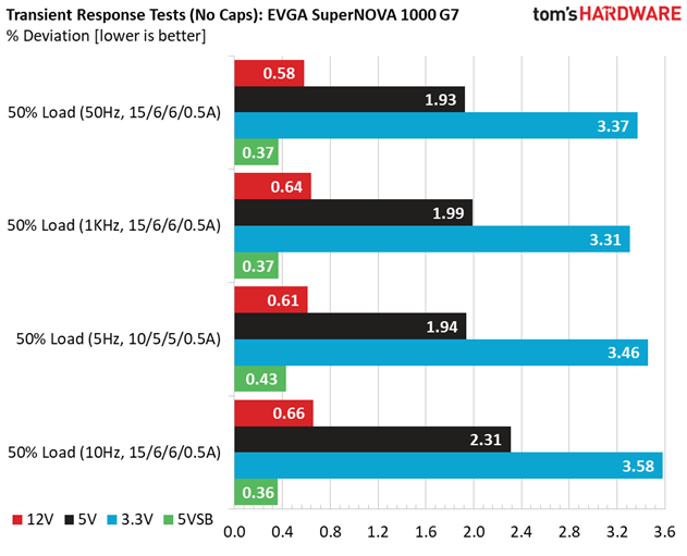
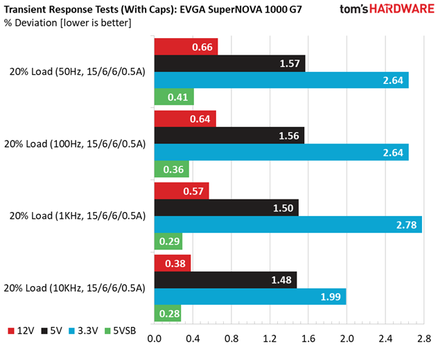
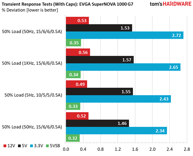
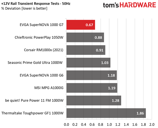
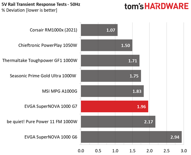
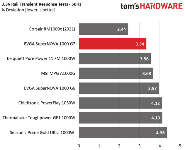
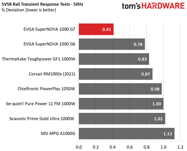
Transient response is good, overall, especially at 12V where it matters the most.
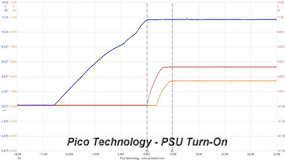
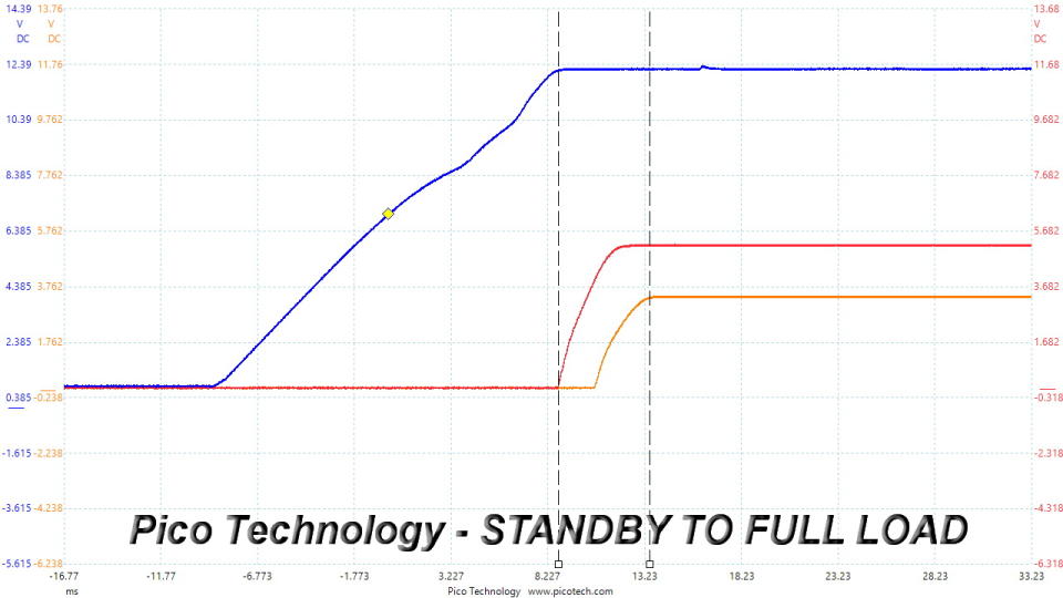
Turn-On Transient Tests
In the next set of tests, we measure the PSU's response in simpler transient load scenarios—during its power-on phase. Ideally, we don't want to see any voltage overshoots or spikes since those put a lot of stress on the DC-DC converters of installed components.
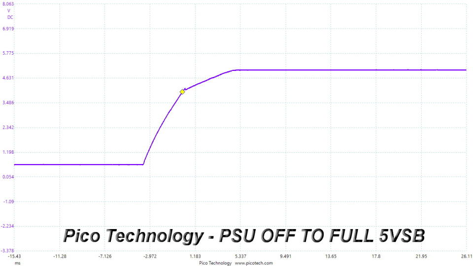
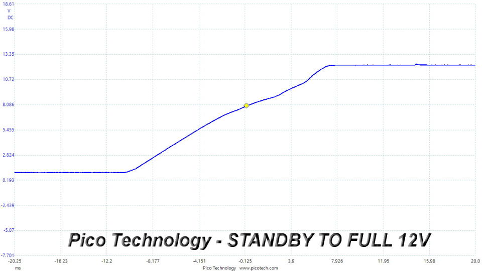
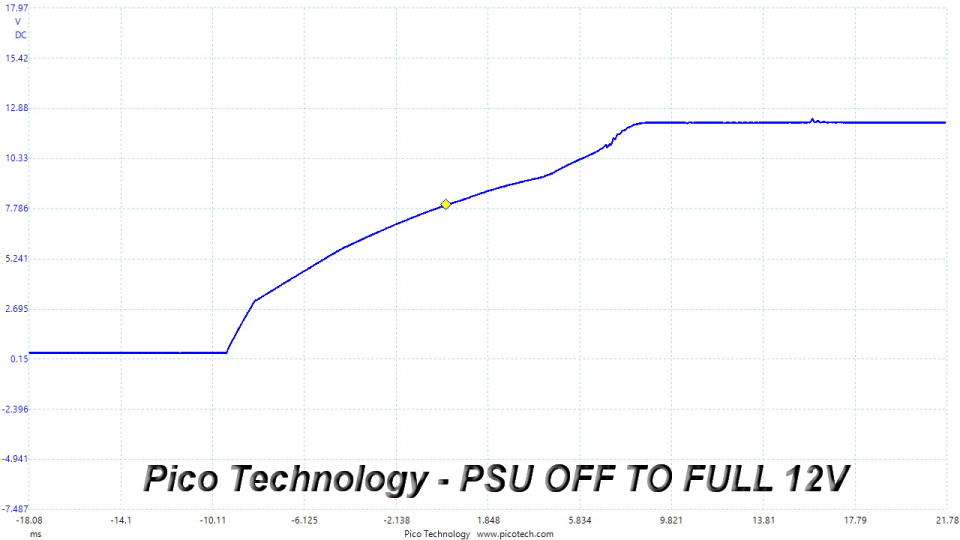
We didn't spot any issues during the turn-on transient tests.
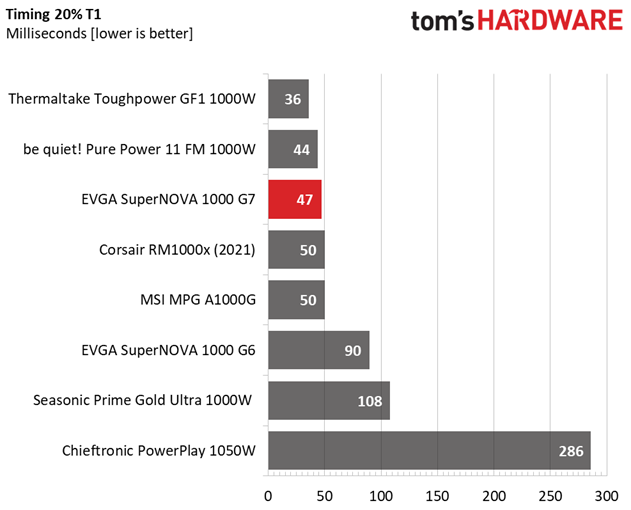
Power Supply Timing Tests
There are several signals generated by the power supply, which need to be within specified, by the ATX spec, ranges. If they are not, there can be compatibility issues with other system parts, especially mainboards. From year 2020, the PSU's Power-on time (T1) has to be lower than 150ms and the PWR_OK delay (T3) from 100 to 150ms, to be compatible with the Alternative Sleep Mode.
T1 (Power-on time) & T3 (PWR_OK delay) | ||
|---|---|---|
T1 | T3 | |
47ms | 129ms | |
43ms | 129ms | |
PSU Timing Charts
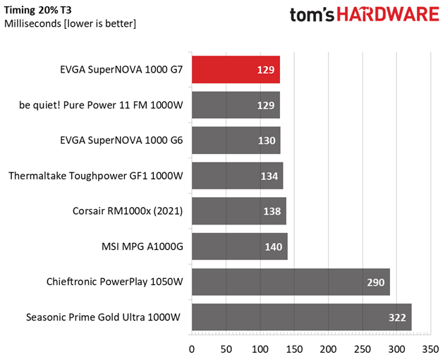
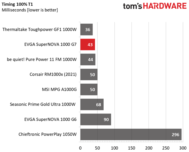
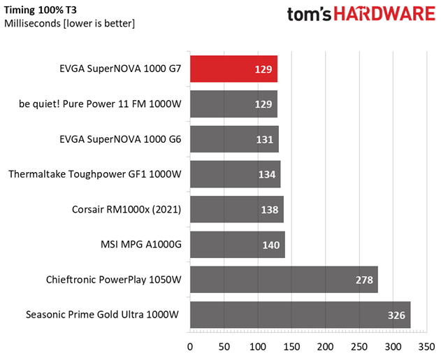
The PWR_OK delay is within the 100-150ms region, so the PSU supports the alternative sleep mode recommended by the ATX spec.
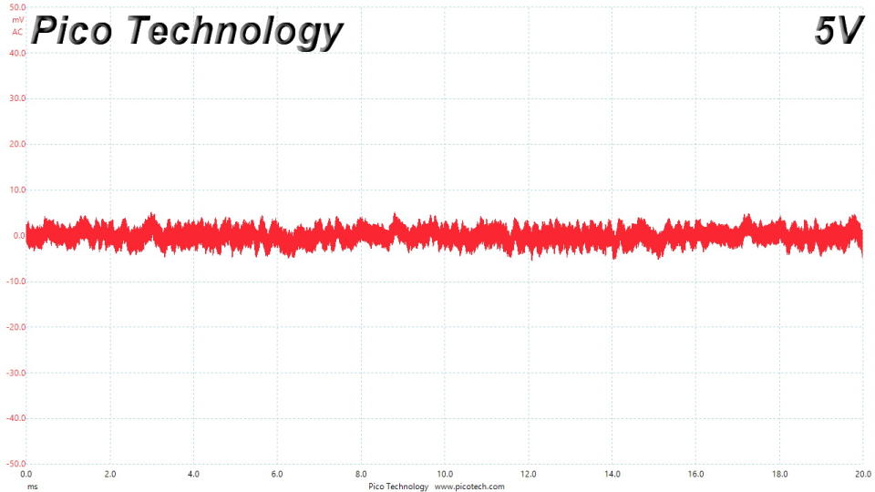
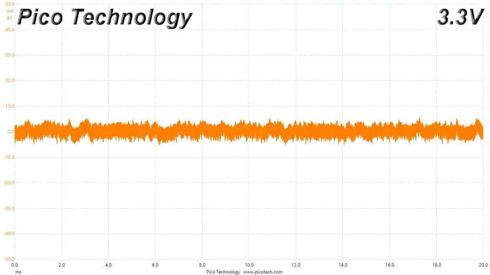
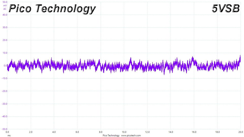
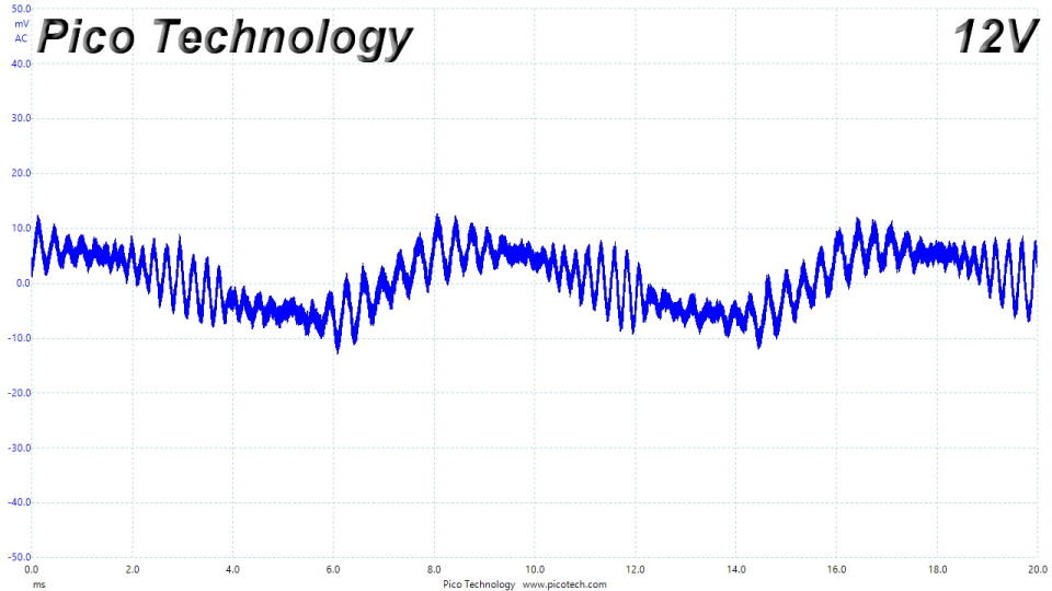
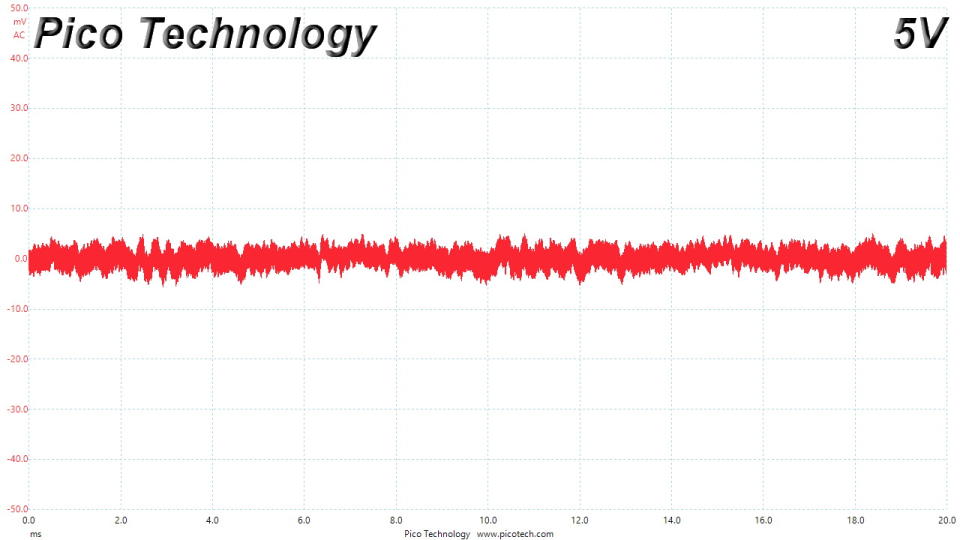
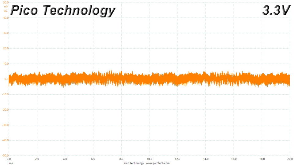
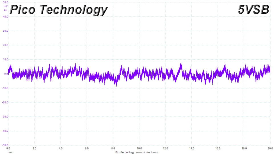
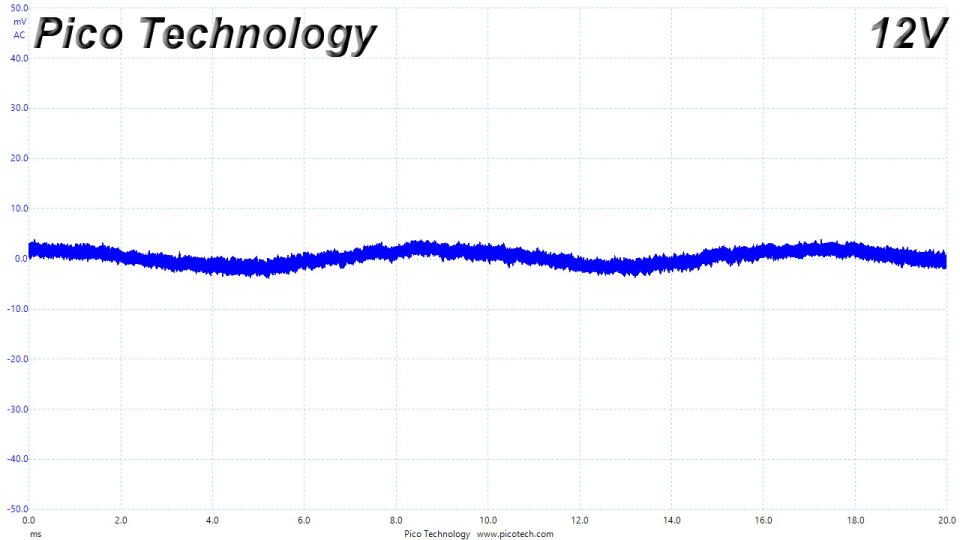
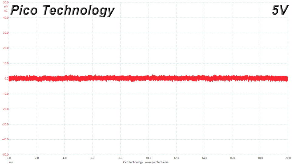
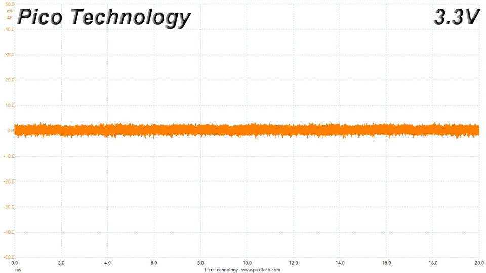
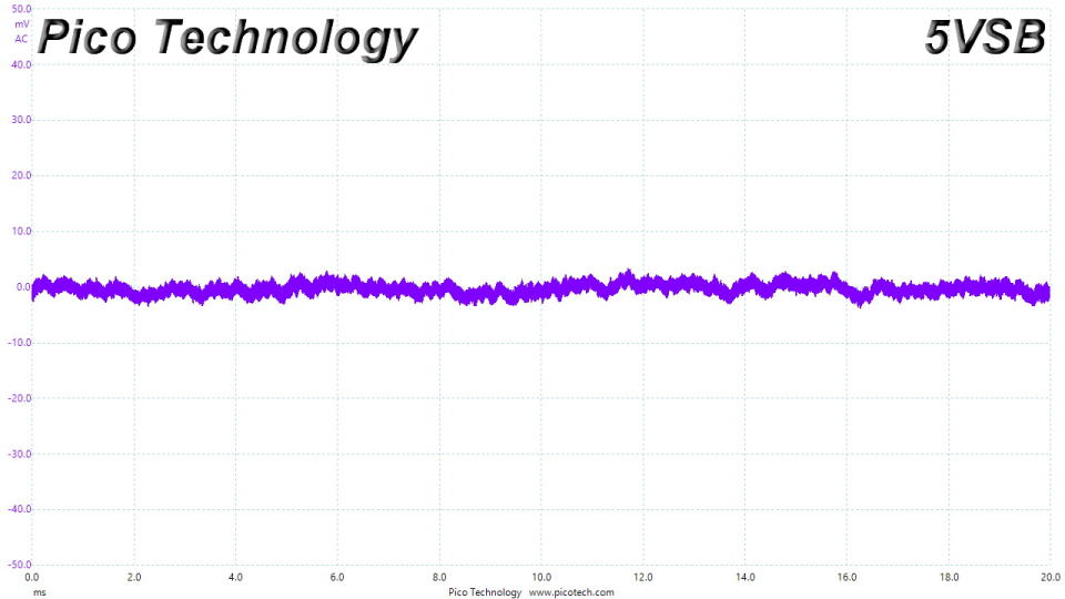
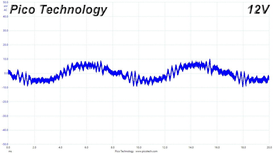
Ripple Measurements
Ripple represents the AC fluctuations (periodic) and noise (random) found in the PSU's DC rails. This phenomenon significantly decreases the capacitors' lifespan because it causes them to run hotter. A 10-degree Celsius increase can cut into a cap's useful life by 50%. Ripple also plays an important role in overall system stability, especially when overclocking is involved.
The ripple limits, according to the ATX specification, are 120mV (+12V) and 50mV (5V, 3.3V, and 5VSB).
Test | 12V | 5V | 3.3V | 5VSB | Pass/Fail |
10% Load | 5.9 mV | 4.7 mV | 4.9 mV | 8.4 mV | Pass |
20% Load | 6.6 mV | 5.5 mV | 6.0 mV | 22.3 mV | Pass |
30% Load | 7.0 mV | 5.5 mV | 6.5 mV | 12.9 mV | Pass |
40% Load | 7.5 mV | 5.9 mV | 6.3 mV | 12.2 mV | Pass |
50% Load | 8.3 mV | 7.3 mV | 7.2 mV | 23.4 mV | Pass |
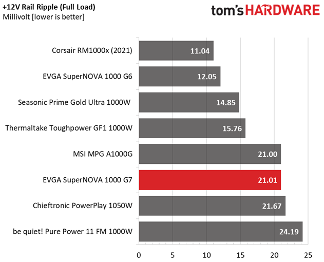
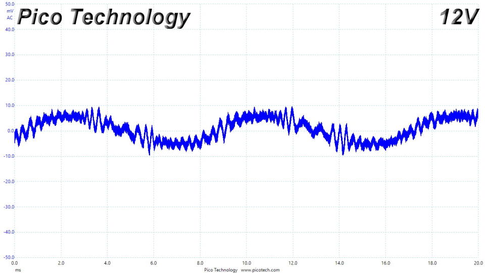
Ripple suppression is good on all rails.
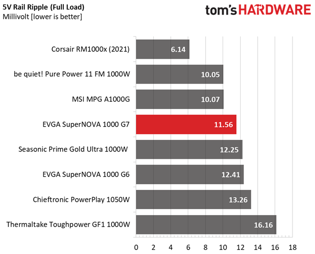
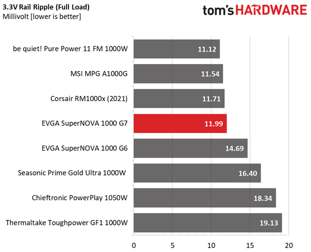
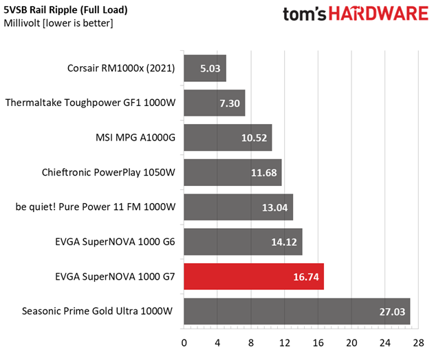
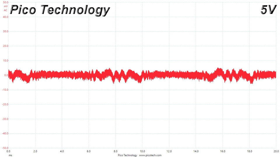
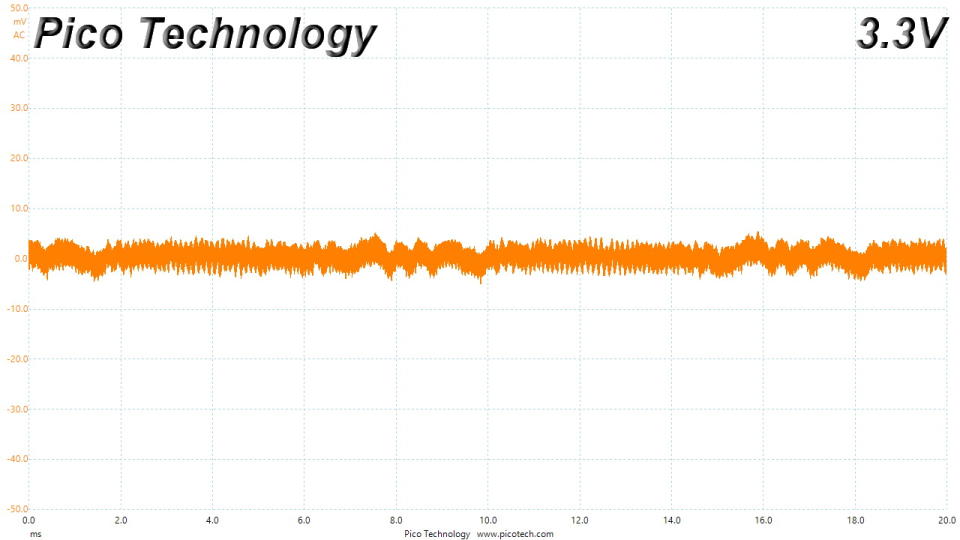
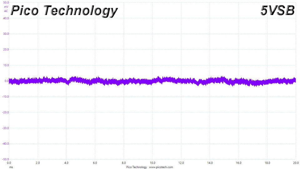
Ripple At Full Load
Ripple At 110% Load
Ripple At Cross-Load 1
Ripple At Cross-Load 4
EMC Pre-Compliance Testing – Average & Quasi-Peak EMI Detector Results
Electromagnetic Compatibility (EMC) is the ability of a device to operate properly in its environment without disrupting the proper operation of other nearby devices.
Electromagnetic Interference (EMI) stands for the electromagnetic energy a device emits, and it can cause problems in other nearby devices if too high. For example, it can cause increased static noise in your headphones or/and speakers.
΅We use TekBox's EMCview to conduct our EMC pre-compliance testing.
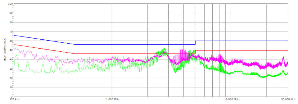
Several spurs exceed the limits with the average EMI detector, but everything is fine with the peak detector.
MORE: Best Power Supplies
MORE: How We Test Power Supplies
MORE: All Power Supply Content
Performance Rating
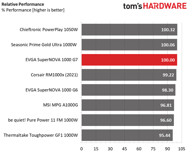
Overall performance is high.
Noise Rating
The graph below depicts the cooling fan's average noise over the PSU's operating range, with an ambient temperature between 30 to 32 degrees Celsius (86 to 89.6 degrees Fahrenheit).
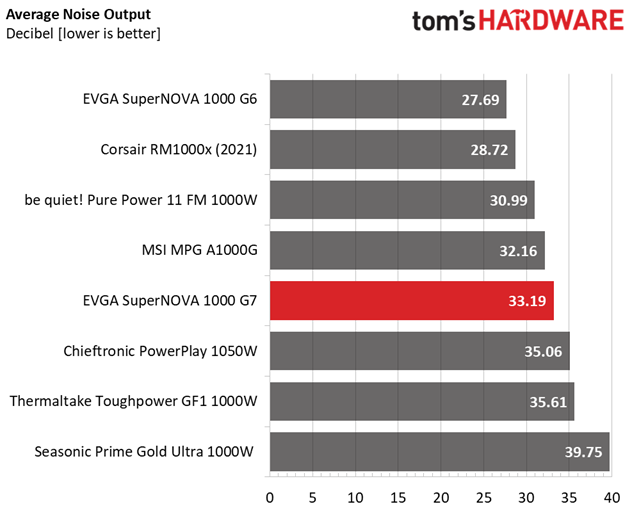
With a larger PCB and fan, this platform could have a lower overall noise output.
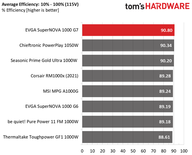
Efficiency Rating
The following graph shows the PSU's average efficiency throughout its operating range with an ambient temperature close to 30 degrees Celsius.
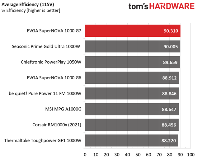
The 1000 G7 is highly efficient and this is why is rated as Platinum in the Cybenetics scale.
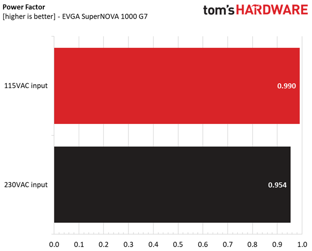
Power Factor Rating
The following graphs show the PSU's average power factor reading throughout its operating range with an ambient temperature close to 30 degrees Celsius and 115V/230V voltage input.
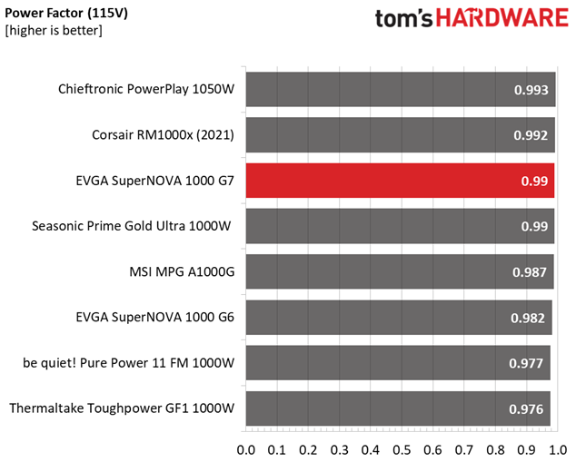
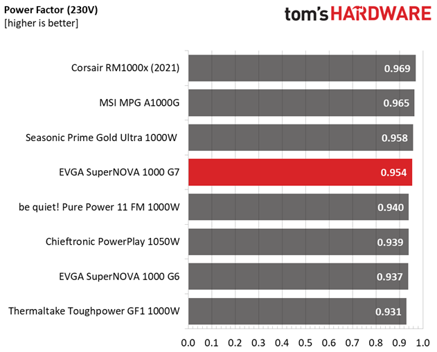
The APFC converter has decent performance.
MORE: Best Power Supplies
MORE: How We Test Power Supplies
MORE: All Power Supply Content
EVGA is near the top spot on our performance charts with the 1000 G7 unit, and this is not an easy feat, considering the mighty Corsair RM1000x that this unit has to face off against. Besides tiny dimensions, the 1000 G7 offers high efficiency, tight enough load regulation, good ripple suppression, and excellent transient response at 12V, which is the most important rail. The build quality is also high, and FSP used top-notch parts, including Rubycon and Chemi-Con caps, along with an FDB fan from a respected manufacturer.
The LED load indicators on the PSU's side are a gimmick, though one that may still come in handy to some. Moreover, PSU downsizing has reached its limits with this product, which is in the SFX-L form factor's territory with only 130 mm depth. Anything less than that will require a smaller fan, and this is not an option if you want to keep noise output low enough. Despite the tiny dimensions, the EVGA 1000 G7 meets the Corsair RM1000x in overall performance, but it loses the fight in noise output because of the smaller fan and the overpopulated PCB. Still, it isn't noisy under normal operating conditions.
MORE: Best Power Supplies
MORE: How We Test Power Supplies
MORE: All Power Supply Content
Disclaimer: Aris Mpitziopoulos is Tom's Hardware's PSU reviewer. He is also the Chief Testing Engineer of Cybenetics and developed the Cybenetics certification methodologies apart from his role on Tom's Hardware. Neither Tom's Hardware nor its parent company, Future PLC, are financially involved with Cybenetics. Aris does not perform the actual certifications for Cybenetics.

