A Complete Guide to Multimeter Symbols
Dzmitrock87 / Getty Images
A multimeter is a must-have tool for electrical projects. The hardest part about learning how to use a multimeter is learning to read the numerous symbols present on a multimeter. Once you can identify each of the multimeter symbols, you can properly select which way to turn the dial, which jacks to utilize, and better understand what the meter is telling you during use.
Reading multimeter symbols isn't as simple as learning what the symbols represent. You must also learn what the terms like ohms, milliamps, capacitance, and more truly mean.
Below, we've laid out the various multimeter symbols and explained what each symbol means so you can operate a multimeter safely and effectively, whether you're using a digital or an analog multimeter.
What Is a Multimeter?
A multimeter is a tool used to measure electrical properties such as resistance, voltage, and current, and test electrical components such as diodes and capacitors.
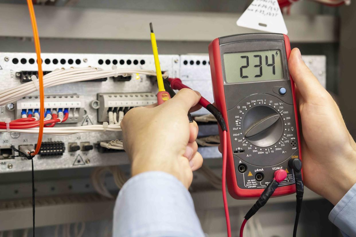
Multimeters feature a dial surrounded by several symbols indicating different electrical values, as well as multiple ports for plugging in electrical leads. To measure and test electrical circuits and components, you must first select the correct symbol on the dial and plug the leads into the correct ports.
Tip
If you're just looking to test an electrical receptacle, a multimeter is overkill. Instead, opt for a plug-in circuit analyzer.
Voltage
Voltage is the pressure that allows electrons to flow from a source and is supplied in both DC (direct current) and AC (alternating current) forms, meaning a multimeter must be able to measure both types of voltage.
Both DC and AC voltage have their advantages and best-use scenarios. As a general rule, you can associate AC voltage with the power in your home and DC voltage with that of a car battery and most electronic devices.
Here is how you tell the difference between AC and DC voltage symbols so you can safely test voltage with a multimeter:
AC Voltage
AC voltage is represented by a V with one wavy line above it.
DC Voltage
DC voltage is represented by a V with two straight lines above it, one dotted and one solid.
Millivolts
mV symbolizes millivolts, which is 1/1000th of a volt.
Warning
Never assume an electrical circuit is dead. Until you've confirmed otherwise, always operate under the assumption that circuit is live.
Current
Current is the flow of electrons through an electrical circuit. Just like voltage, current is either AC or DC and a multimeter is equipped to measure both.
Both AC and DC currents are measured in amps, which refers to the volume of electrons flowing through the circuit. An amp is the difference between voltage and resistance, so you can also find the amount of amps in a circuit by first finding the voltage and the resistance of the circuit, and then dividing the volts by the resistance (ohms).
Here are the different symbols indicating different forms of currents on a multimeter:
Milliamps
Milliamps are represented by the symbol mA. A milliamp is 1/1000th amp.
Microamps
Microamps are represented by the symbol µA. A microamp is 1/1,000,000th amp.
AC Current
AC current is represented by an A with one wavy line above it.
DC Current
DC current is represented by an A with two straight lines above it, one dotted and one solid.
Resistance
Resistance is the opposition of the flow of electrons through an electrical circuit. Multimeters measure resistance by sending an electric current through a circuit. The resistance is then presented in ohms.
Because different electrical circuits can have vastly different resistances, there are multiple stages of measurement on a multimeter.
Here are the following common resistance options on a standard multimeter and their associated symbols:
Ohms
Ohms are represented by the Ω symbol.
Kilohms
Kilohms are represented by kΩ and are equal to 1,000 ohms.
Megaohms
Megaohms are represented by MΩ and are equal to 1,000,000 ohms.
Continuity Test
A multimeter can test for continuity, which shows if an electrical signal is successfully traversing the circuit. This is beneficial for many situations, such as checking if a fuse is blown or an electrical component is failing.
To find the continuity test function, look for a symbol that resembles a Wi-Fi symbol on its side. When performing a continuity test, the result will either be open, which indicates a broken circuit, or closed, which indicates an intact circuit.
If the multimeter can complete the circuit, a 0.000 will appear on the screen, often joined by a continuous beep.
Diode and Capacitance Test
Multimeters can also test electrical components like diodes and capacitors and some can even measure the temperature. To find these test functions, look for the following symbols:
Diode Test
The diode test is represented by a symbol resembling a right-facing arrow pointing at a cross, both situated on a horizontal line. Diodes are electrical components responsible for converting AC into DC. Running a diode test will indicate whether or not the diodes are working.
Capacitance Test
Capacitors are electrical components that store a charge. Testing capacitors can measure the stored charge. To perform a capacitance test, look for a symbol that features a vertical line to the left of what looks like a right-facing parenthesis, with a horizontal line crossing through both.
Temperature
Some multimeters can even measure the temperature, which is useful for anything from measuring the temperature of the ambient air to measuring the temperature of a transformer or electrical wire. A thermometer symbol will indicate the temperature setting.
Typically, a multimeter that can measure temperature will come equipped with a thermocouple with two leads that plug into jacks on the multimeter. On the other end of the thermocouple is a wire attached to a temperature probe.
Multimeter Jacks
To use a multimeter, you must insert the red and black leads into the appropriate jack for the task at hand. Sticking the leads into the wrong jacks and simply turning the dial to the position of your desired task won't work. Most multimeters have three jacks, though some may have four.
Here are the usual jacks found on a standard multimeter tool and what each one is used for:
COM
COM stands for common and is always reserved for the black lead.
A
Place the red lead in the A jack to measure high current up to 10 amps. This port may also be labeled 10A.
mAVΩ
The mAVΩ jack is used for the red lead when measuring voltage, resistance, and temperature. If the multimeter is limited to three jacks, this jack is also utilized for measuring sensitive currents like milliamps and microamps.
mAµA
If the multimeter has a fourth jack labeled mAµA, use this instead for measuring microamps and milliamps.
VΩ
If the mAµA port is present, it will likely have a port beside it labeled VΩ. In this case, this jack is utilized for voltage and resistance.
Other Multimeter Buttons
Different multimeters have different functions, but you can count on these other buttons being present on nearly every multimeter:
Shift
The SHIFT button is much like the shift button on a computer keyboard. It unlocks the second function of many of the symbols on the dial. To read the multiple second functions, look for writing written in a secondary color above or below the primary dial functions. On some multimeters, the shift button is called a function button or Fn.
Hold
The HOLD button is used to freeze whatever reading is currently on the screen. This allows you to reference the reading later on.
Manual vs. Auto Range Multimeters
Auto-range multimeters automatically select the range of the values being tested. On the contrary, a manual range multimeter requires the user to select the range of the value being tested (200Ω, 20kΩ, 200kΩ, etc). This was necessary on older multimeters which utilize a needle to display the measurement rather than a digital readout.
Auto-range multimeters are a more modern invention and were once considered less accurate, less sensitive, and less trustworthy than manual-range multimeters. Nowadays, auto-range multimeters are generally considered to be nearly 100% accurate. As you may have guessed, auto-range multimeters are quicker and easier to use than manual multimeters.
Read Next: 20 Top Tools You May Need for Electrical Projects
Read the original article on The Spruce.

